
Why Is a Pilot-Operated Check Valve a Hydraulic Lock?
In hydraulic systems, controlling fluid direction is only one part of achieving safe and reliable motion. Equally important is the ability to stop an actuator at a predetermined position and keep it there when the pump is unloaded, the directional control valve changes position, or the hydraulic power unit is shut down. This requirement becomes particularly important when a cylinder is carrying a suspended or elevated load.
A conventional check valve can prevent fluid from flowing in one direction, but it cannot normally be opened from the reverse direction without changing the system configuration. A pilot-operated check valve, by contrast, introduces an external hydraulic control signal that allows the normally blocked flow path to be opened when required. This combination of automatic one-way shutoff and externally controlled release is the fundamental reason that the component is often described as a "hydraulic lock."
The term does not mean that the valve creates an absolutely immovable mechanical lock. Rather, it describes its ability to hydraulically isolate an actuator from the rest of the circuit and thereby hold its position under suitable design and operating conditions. The actual holding accuracy depends on valve leakage, fluid compressibility, cylinder leakage, hose expansion, pressure changes, load characteristics, and the overall hydraulic circuit.
Understanding this distinction is essential when selecting a pilot-operated check valve for industrial machinery, lifting equipment, mobile hydraulics, hydraulic presses, injection molding machines, and other applications where controlled load holding is required.
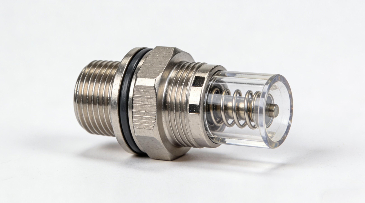
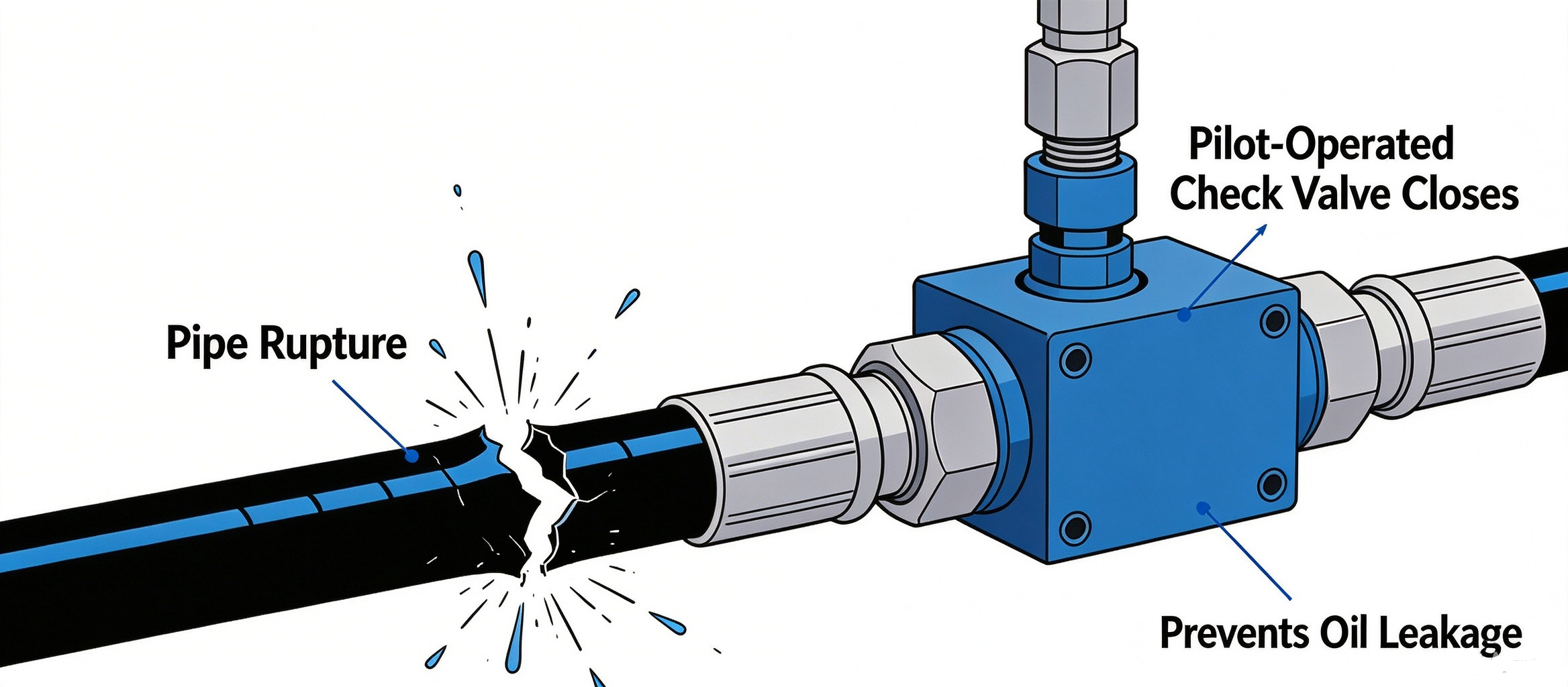
A pilot-operated check valve is a specialized check valve that allows free or relatively low-resistance flow in one direction while blocking flow in the opposite direction until an external pilot pressure is applied.
Its basic structure is derived from the conventional check valve but incorporates additional hydraulic control elements. Depending on the design, the main components may include a valve body, poppet or ball, seat, spring, pilot piston, pilot port, and sometimes an auxiliary unloading element.
Under normal conditions, the spring and system pressure keep the main poppet or ball against its seat. Fluid can pass through in the permitted direction, but reverse flow is blocked.
When sufficient pilot pressure is introduced through the control port, the pilot piston generates a mechanical force that moves the main poppet away from its seat. The previously blocked flow path is then opened.
This creates two distinct operating states:
| Operating Condition | Main Valve Behavior | Hydraulic Function |
|---|---|---|
| No pilot pressure | Reverse flow blocked | Load holding |
| Pilot pressure applied | Main check element opens | Controlled reverse flow |
| Pilot pressure removed | Valve returns toward closed position | Hydraulic isolation |
| Pressure differential present | Check action assists closure/opening depending on flow direction | Automatic flow control |
This operating principle combines the automatic behavior of a check valve with the controllability of a directional valve.
The term "hydraulic lock" comes from the valve's ability to trap hydraulic fluid on one side of an actuator.
Consider a hydraulic cylinder supporting a vertical load. If the cylinder is connected directly to a directional control valve, the cylinder may gradually move after the control valve returns to neutral because every hydraulic component has some degree of internal leakage.
A pilot-operated check valve can be installed close to the cylinder ports. When the control signal is removed, the check valve blocks the relevant flow path and isolates the cylinder chamber. The trapped hydraulic fluid prevents the cylinder from freely discharging through the directional control valve.
The resulting arrangement resembles a mechanical lock:
Load → Hydraulic cylinder → Trapped fluid → Pilot-operated check valve → Closed flow path
As long as the valve remains properly seated and the rest of the hydraulic components maintain their integrity, the actuator can remain in position for an extended period.
However, engineers should avoid interpreting this as an absolute guarantee of zero movement. Hydraulic systems contain compressible elements, including oil, hoses, seals, and trapped gas. Thermal expansion and small leakage rates can also cause gradual movement. Therefore, safety-critical load holding should be evaluated using the complete circuit design and appropriate safety devices.
The operation can be understood in three basic stages.
During normal operation, hydraulic fluid flows through the permitted direction of the check valve. The valve's spring and pressure differential determine the position of the poppet or ball.
The valve therefore behaves much like a conventional check valve.
For example, hydraulic oil can flow from a pump or directional valve toward a cylinder chamber while reverse flow from the cylinder toward the control valve is blocked.
When the directional control valve moves to a neutral position or the pump stops supplying flow, the pilot pressure disappears or decreases according to the circuit configuration.
The main check element moves onto its seat, preventing reverse flow. The fluid trapped in the cylinder chamber then supports the load.
This is the key hydraulic-lock function.
When the operator commands the actuator to move in the opposite direction, pilot pressure is introduced to the pilot port.
The pilot piston applies force to the main valve element. Once the pilot force is sufficient to overcome the relevant spring and hydraulic forces, the main check element opens and allows the trapped fluid to leave the cylinder chamber.
The cylinder can then move in a controlled manner.
This sequence can be summarized as:
Pilot pressure ON → Check valve opens → Fluid can return → Actuator moves
Pilot pressure OFF → Check valve closes → Fluid is trapped → Actuator holds
The two valve types share the same basic check-valve principle, but their functions are substantially different.
A conventional check valve is designed primarily for automatic one-way flow control. It opens when pressure in the permitted direction overcomes the spring and opposing pressure, and closes when the flow reverses.
A pilot-operated check valve adds a control mechanism that allows the normally blocked direction to be opened intentionally.
| Feature | Conventional Check Valve | Pilot-Operated Check Valve |
|---|---|---|
| Forward flow | Permitted | Permitted |
| Reverse flow | Blocked | Blocked until pilot pressure is applied |
| External control | No | Yes |
| Load holding | Limited to circuit application | Stronger and more controllable |
| Controlled reverse flow | Not normally available | Available through pilot pressure |
| Typical application | Backflow prevention | Load holding and actuator locking |
| Circuit complexity | Low | Higher |
| Pilot pressure requirement | None | Required |
The pilot-operated design is therefore particularly useful when an actuator must both hold its position and be intentionally released.
Position holding is one of the most important applications for pilot-operated check valves.
Consider a double-acting hydraulic cylinder installed in a lifting mechanism. When hydraulic pressure is applied to extend the cylinder, the load rises. Once the desired position is reached, the directional valve returns to neutral.
Without an effective load-holding mechanism, pressure can gradually decay through valve leakage or other circuit paths. The cylinder may slowly retract under the influence of gravity.
Installing pilot-operated check valves at the cylinder ports can isolate the cylinder chambers. The load is then hydraulically supported by trapped oil.
This arrangement is commonly used in:
- Hydraulic lifting platforms
- Material handling equipment
- Hydraulic clamps
- Machine tools
- Industrial presses
- Agricultural machinery
- Construction equipment
- Mobile hydraulic systems
For critical applications, however, engineers should distinguish between position holding and personnel safety. A pilot-operated check valve should not automatically be regarded as a substitute for a mechanical locking device, safety prop, or other required safety mechanism.
Vertical cylinders create a particularly important safety challenge because gravity continuously acts on the load.
If a hydraulic line fails between the directional valve and the cylinder, a conventional circuit may allow hydraulic fluid to escape rapidly. The cylinder could then move unexpectedly.
A pilot-operated check valve located close to the actuator can limit uncontrolled flow by closing when pilot pressure is lost.
However, the exact response to a hose failure depends on the valve configuration and the failure scenario. A standard pilot-operated check valve may require a pressure condition that is not available during certain catastrophic line failures. For applications specifically requiring protection against hose rupture or uncontrolled descent, engineers may instead use or combine hose-burst valves, velocity fuses, counterbalance valves, load-holding valves, or other dedicated safety components.
The appropriate device should therefore be selected according to the actual hazard and applicable machinery safety requirements.
Pilot pressure is one of the most important technical parameters when selecting a pilot-operated check valve.
The pilot piston has an effective area that converts pilot pressure into a mechanical opening force. The relationship between the pilot area and the main valve area determines how much pilot pressure is required to release the valve under a given load condition.
This relationship is commonly described using a pilot ratio.
A simplified conceptual relationship can be expressed as:
Pilot force ≈ Pilot pressure × Pilot piston area
The valve must generate sufficient pilot force to overcome the forces keeping the main check element closed.
In a real hydraulic circuit, the required pilot pressure depends on more than the pilot ratio. Engineers must also consider:
- Load-induced pressure at the cylinder port
- Spring force
- Valve geometry
- Back pressure
- Pressure differential
- Cylinder area ratio
- Dynamic operating conditions
- Pilot line pressure losses
Incorrect pilot-ratio selection can lead to either failure to open or undesirable operating characteristics.
Pilot-operated check valves may be configured so that the pilot pressure is generated directly from another hydraulic line or supplied through an external control circuit.
The choice depends on the desired operating sequence and the hydraulic architecture.
A direct pilot arrangement can provide relatively straightforward control. However, the pilot signal must remain available under the required operating conditions.
An external pilot arrangement can provide greater flexibility, particularly when the designer needs to coordinate valve release with a separate control signal.
In complex hydraulic systems, the pilot circuit should be analyzed as carefully as the main flow circuit because insufficient pilot pressure can prevent the actuator from moving even when the main pump and directional valve are functioning normally.
Pilot-operated check valves can be configured for one cylinder port or both ports.
A single valve may be sufficient when only one direction of actuator movement requires hydraulic locking.
For example, a vertical cylinder may require positive holding in the lowering direction while movement in the opposite direction is controlled through another circuit element.
For applications requiring both cylinder chambers to be hydraulically locked, a dual configuration can be used.
A dual pilot-operated check valve assembly is often installed directly on the cylinder ports. The pilot signal from one side can release the check valve on the opposite side, allowing coordinated movement.
This arrangement is particularly useful for double-acting cylinders where both extension and retraction positions must be maintained when the directional valve is in neutral.
The location of a load-holding valve can be just as important as the valve itself.
For load-holding applications, placing the valve close to the actuator can minimize the volume of hydraulic fluid between the locking valve and the cylinder.
This arrangement can provide several advantages:
- Reduced uncontrolled fluid volume.
- Faster isolation of the actuator.
- Less influence from long hose expansion.
- Better protection against certain line failures.
- Improved position-holding characteristics.
If the valve is installed far away from the cylinder, a long length of hose remains between the actuator and the locking point. Hose expansion and trapped fluid can then influence the actual movement of the actuator.
For critical applications, engineers should therefore evaluate the entire hydraulic volume between the actuator and the load-holding valve.
Pilot-operated check valves can also differ in how pilot leakage or control fluid is handled.
The choice between internal drain and external drain is important when significant back pressure may occur at the valve outlet.
In an internal-drain configuration, the drain path is connected internally to another pressure region. If downstream back pressure rises significantly, it can influence the effective forces acting on the pilot mechanism.
An externally drained configuration provides a separate drain connection, allowing the pilot mechanism to discharge to a lower-pressure reservoir or another appropriate circuit location.
Engineers should consider external drain arrangements when:
- Back pressure is relatively high.
- The valve operates under significant pressure fluctuations.
- Accurate pilot control is required.
- The hydraulic circuit contains complex return-line pressure.
- The manufacturer specifies an external drain arrangement.
Ignoring drain pressure can result in unexpected valve behavior, including failure to open or unstable operation.
The directional control valve and pilot-operated check valve must be designed as a coordinated system.
When the directional valve returns to neutral, the pilot pressure must fall sufficiently for the load-holding valve to close. If the directional valve traps pilot pressure, the pilot-operated check valve may remain partially or fully open.
This is why the center condition of a four-way directional control valve is important.
Depending on the hydraulic circuit, H-center or Y-center configurations may provide a suitable path for pressure unloading. However, the correct center condition cannot be selected solely because it is commonly associated with hydraulic locks. It must be evaluated together with the pump type, actuator configuration, pilot circuit, pressure requirements, and desired neutral-state behavior.
A detailed circuit analysis is therefore necessary before specifying the directional valve center position.
Pilot-operated check valves and counterbalance valves are sometimes confused because both can contribute to load holding. Their operating principles and preferred applications, however, are different.
A pilot-operated check valve is primarily intended to block flow and hold an actuator when the pilot signal is absent.
A counterbalance valve is designed to control load-induced flow and maintain a controlled pressure condition, particularly in overrunning-load applications. It can help prevent a vertical or suspended load from running away faster than the pump can supply fluid.
For example, a hydraulic motor driving an overrunning load or a cylinder lowering a heavy load may require controlled back pressure rather than simple isolation.
The choice should therefore be based on the dynamic behavior of the load.
Lifting systems provide a clear example of why hydraulic locking matters.
Suppose a hydraulic cylinder raises a platform carrying several hundred kilograms of equipment. When the platform reaches the required height, the operator releases the control lever.
The hydraulic system must prevent the cylinder from retracting unintentionally. A pilot-operated check valve can isolate the cylinder chamber and retain hydraulic pressure.
The system may therefore remain stable while the pump is unloaded.
However, lifting applications often involve personnel, suspended loads, and serious hazards. A hydraulic lock alone should not be assumed to provide complete safety. Depending on the equipment design, additional mechanical supports, emergency lowering systems, hose-burst protection, pressure relief devices, and other safety measures may be required.
Aerial work platforms and other lifting equipment frequently require reliable load holding because the working platform may remain elevated for extended periods.
Pilot-operated check valves can help prevent unintended cylinder movement when the control system is neutral.
In such equipment, the valve may be installed close to the cylinder and integrated with other load-control devices. The objective is to minimize uncontrolled movement under normal operation and certain fault conditions.
The complete circuit should nevertheless be validated under emergency scenarios, including loss of pilot pressure, hose rupture, power failure, and sudden load changes.
Hydraulic presses require controlled cylinder positioning and high force. During a pressing operation, the cylinder may need to remain at a specified position while the hydraulic system maintains pressure.
A pilot-operated check valve can provide a controlled means of isolating the cylinder chamber during holding stages.
In addition to position holding, the hydraulic circuit may require pressure relief, synchronization, pressure compensation, or controlled decompression. The pilot-operated check valve therefore forms only one part of the overall hydraulic control architecture.
Injection molding equipment involves repeated high-pressure hydraulic operations and precise actuator movement. Hydraulic cylinders and other actuators may need to maintain position during different stages of the molding cycle.
Pilot-operated check valves can be used where hydraulic isolation and pressure retention are required.
Because injection molding systems frequently operate at high cycle rates, the valve must be selected for appropriate response characteristics, pressure rating, flow capacity, and fatigue resistance.
Valve sizing should account not only for maximum pressure but also for peak flow rates and the dynamic behavior of the machine.
Agricultural machinery and mobile hydraulic equipment often operate under highly variable conditions. Cylinders may support implements, booms, buckets, stabilizers, or other loads.
These applications may experience vibration, shock, contamination, temperature changes, and long hose runs.
Pilot-operated check valves can provide localized load holding while reducing dependence on the leakage characteristics of the directional control valve.
For mobile equipment, however, compactness, contamination resistance, response time, pressure rating, and ease of maintenance are particularly important selection criteria.
A common engineering mistake is selecting a pilot-operated check valve solely according to system pressure.
A complete specification should also include the required flow rate. An undersized valve can create excessive pressure drop and heat generation. An oversized valve may produce poor control characteristics or unnecessary cost.
Important parameters include:
| Parameter | Why It Matters |
|---|---|
| Maximum working pressure | Determines pressure capability |
| Maximum flow rate | Determines valve size and pressure drop |
| Pilot pressure | Determines opening behavior |
| Pilot ratio | Determines required control pressure |
| Fluid viscosity | Influences flow resistance |
| Temperature | Affects fluid and seal performance |
| Leakage rate | Influences long-term position holding |
| Port size | Must match hydraulic piping |
| Mounting configuration | Affects installation and maintenance |
| Material compatibility | Determines service durability |
The valve should be selected using actual operating data rather than nominal system specifications alone.
The hydraulic fluid has a direct influence on valve service life.
Mineral-based hydraulic oils are common in industrial systems, but water-glycol fluids, biodegradable hydraulic fluids, and other specialized media are also used.
Seal materials must be compatible with the selected fluid and operating temperature. Chemical incompatibility can cause swelling, hardening, cracking, or accelerated degradation.
Contamination is another major concern. Dirt and metallic particles can damage precision valve seats and pilot passages. Because pilot-operated check valves contain relatively small control passages, contamination can interfere with pilot operation even when the main flow path remains functional.
Although these valves provide reliable load holding when properly selected, several failure modes can occur.
Possible causes include insufficient pilot pressure, incorrect pilot ratio, blocked pilot passage, excessive back pressure, damaged pilot piston, or incorrect directional valve configuration.
Possible causes include contamination on the seat, damaged sealing surfaces, residual pilot pressure, mechanical sticking, or incorrect circuit design.
Internal leakage may result from worn seats, damaged poppets, contamination, erosion, or seal deterioration.
A valve that is too small for the required flow may create excessive pressure loss and heat generation.
Incorrect pilot pressure, unsuitable valve configuration, trapped air, excessive load-induced pressure, or inappropriate valve sizing can produce unstable movement.
Diagnosing the root cause is preferable to simply replacing the valve because the same circuit condition may damage a replacement valve again.
A preventive maintenance program should include regular inspection of the valve and the surrounding hydraulic circuit.
Recommended activities include:
- Check for external leakage.
- Monitor abnormal temperature rise.
- Verify actuator holding performance.
- Inspect hydraulic oil cleanliness.
- Check pilot pressure.
- Verify directional valve operation.
- Inspect hoses and fittings.
- Check for abnormal cylinder drift.
- Review operating pressure and flow.
- Replace damaged sealing components according to the manufacturer's requirements.
For critical equipment, maintenance personnel should establish baseline performance and monitor changes over time.
A systematic selection process can significantly reduce application problems.
Determine the maximum static and dynamic load that the hydraulic cylinder or actuator must hold.
Establish normal, maximum, and transient pressures rather than relying only on nominal pump pressure.
Determine the maximum flow required during actuator extension and retraction.
Confirm that the directional valve and pilot circuit can provide enough pressure to open the check valve under the worst-case load condition.
Balance the required opening pressure with the desired load-holding characteristics.
Check whether return-line pressure could interfere with the pilot mechanism.
Choose the appropriate configuration based on circuit pressure and manufacturer's recommendations.
Determine whether the application also requires counterbalance valves, hose-burst protection, mechanical locks, or other safety devices.
Hydraulic locking is extremely useful, but it should not be confused with a physical mechanical lock.
A hydraulic lock depends on fluid pressure, valve integrity, seals, and the hydraulic circuit. A mechanical lock physically prevents movement through a solid structural component.
For applications involving personnel beneath suspended loads or other high-consequence hazards, hydraulic locking may need to be supplemented with mechanical means of support.
This distinction is particularly important during maintenance. Before personnel enter a hazardous area, the equipment should be placed into the appropriate safe state according to the manufacturer's procedures and applicable workplace safety requirements.
A pilot-operated check valve is much more than a conventional check valve with an additional control port. Its ability to combine automatic one-way flow control, externally controlled release, and hydraulic load holding makes it a critical component in many hydraulic systems.
It is commonly called a "hydraulic lock" because, when pilot pressure is absent, the valve can isolate an actuator chamber and trap hydraulic fluid, helping prevent unwanted movement. When pilot pressure is applied, the valve can be intentionally released so that the actuator can move again.
This operating principle makes pilot-operated check valves valuable in lifting equipment, hydraulic presses, injection molding machinery, agricultural machinery, mobile equipment, machine tools, and many other applications.
However, reliable hydraulic locking depends on the entire circuit rather than the valve alone. Engineers must consider pilot ratio, pressure, flow, back pressure, leakage, valve location, fluid cleanliness, sealing materials, directional valve center condition, cylinder load, and safety requirements.
The most important selection principle is therefore to treat the pilot-operated check valve as part of an integrated hydraulic system. When correctly sized, installed close to the actuator where appropriate, supplied with adequate pilot pressure, and combined with suitable safety and load-control devices, it can provide dependable position holding and controlled actuator release.
That is the engineering meaning behind the familiar term "hydraulic lock": not simply stopping fluid flow, but using controlled hydraulic isolation to make actuator movement predictable, stable, and manageable.

BALTIC VALVE CO., LTD supplies superior quality industrial valves covering ball valves, globe valves, gate valves, check valves, plug valves, butterfly valves, marine valves, forging steel valve, filter, etc.


PTFE vs. EPDM for Industrial Valves
Sep 18, 2026

Valve Type and Actuator Torque Selection
Sep 06, 2026
Baltic Valve Co., Ltd.
Add: Baltic Valve Park, Siming, Xiamen, China.
Tel: +86 592 8266 140
Fax: +86 592 8266 440
Mail: [email protected]
Website: https://www.baltic-valve.com
Copyright © 2017-2026 Baltic Valve Co., Ltd. All rights reserved. Privacy Policy | Terms of Service
Website Design & Support: jeawin.com