
Ventilation Butterfly Valves: A Practical Guide
Ventilation butterfly valves regulate airflow in industrial ducts, building ventilation systems, HVAC installations, and exhaust networks. Their compact structure, quarter-turn operation, and compatibility with manual or automated actuators make them an efficient solution for airflow control, but their leakage performance and pressure resistance depend on the design and operating conditions. Selecting the right valve requires evaluating duct size, air velocity, differential pressure, temperature, material compatibility, sealing requirements, and control accuracy.
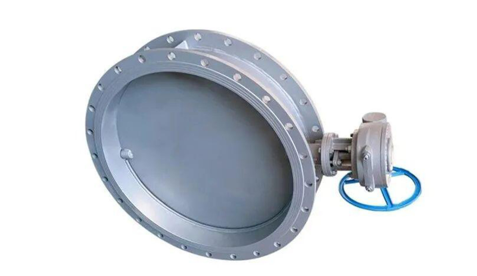
A ventilation butterfly valve is a rotary flow-control device installed in an air duct or ventilation pipeline. It uses a disc mounted on a shaft to regulate airflow by changing the available flow area. Depending on the design, it may serve as an airflow regulator, an isolation device, or part of an automated ventilation control system.
Ventilation butterfly valves are commonly found in commercial buildings, factories, warehouses, industrial exhaust systems, and air-handling equipment. They can regulate fresh-air intake, exhaust discharge, recirculated air, and airflow distribution between different duct branches.
Unlike a conventional gate valve, which moves a closure element linearly, a butterfly valve operates through rotational movement. A quarter-turn mechanism typically moves the disc between the fully open and fully closed positions, although intermediate positions can also be used to adjust airflow.
It is important to distinguish a ventilation butterfly valve from a general-purpose industrial butterfly valve. Some ventilation valves are designed primarily for low-pressure air distribution, while industrial butterfly valves may be engineered for higher differential pressures, elevated temperatures, corrosive process gases, or more demanding shutoff requirements. Their construction and performance ratings are not automatically interchangeable.
Ventilation butterfly valves perform several important functions.
- Airflow regulation: Adjusting the disc position changes the resistance to airflow and helps distribute air according to system requirements.
- Airflow isolation: Suitable designs can restrict or stop airflow through a duct section during maintenance or shutdown.
- Pressure balancing: Adjusting flow resistance can help maintain the intended airflow distribution and pressure relationships between duct branches.
- Automated ventilation control: Electric or pneumatic actuators can position the disc in response to control signals.
- Energy management: Appropriate airflow control can help reduce unnecessary ventilation and support more efficient operation of fans and air-handling equipment.
The effectiveness of these functions depends on the valve's aerodynamic characteristics, leakage performance, actuator sizing, and installation conditions.
The operating principle is straightforward: a disc rotates around a shaft to change the effective opening through which air passes. The disc position determines the available flow area and influences the pressure loss across the valve.
A typical ventilation butterfly valve consists of five principal components.
1. Valve body
The body supports the internal components and connects the valve to the duct or pipeline. Depending on the application, the body may be made from carbon steel, stainless steel, galvanized steel, aluminum, or another suitable material.
The body must withstand the mechanical loads and differential pressures associated with the intended service. For corrosive exhaust systems, material selection should also account for moisture, chemical contaminants, and the operating temperature.
2. Butterfly disc
The disc is the main flow-regulating element. When fully open, it generally presents a relatively small obstruction to the airflow, although the disc and shaft still create some pressure loss.
As the disc rotates toward the closed position, it increasingly restricts the passage. The disc profile, thickness, edge geometry, and position relative to the shaft all influence airflow behavior, pressure loss, and operating torque.
3. Shaft
The shaft transmits torque from the operating mechanism to the disc. Its strength, alignment, bearing arrangement, and corrosion resistance affect operating reliability.
For large-diameter valves, shaft deflection and bearing friction can become significant design considerations. A shaft that is inadequately sized or poorly supported may cause uneven disc movement, increased actuator demand, or sealing problems.
4. Actuator or operating mechanism
The actuator supplies the torque needed to position the disc. Depending on the application, the valve may use a manual lever, gearbox, electric actuator, or pneumatic actuator.
Manual operation is often adequate for small or infrequently adjusted valves. Automated systems generally require actuators that can respond to control signals and provide the necessary positioning accuracy, operating torque, and fail-safe behavior where specified.
5. Seat or sealing arrangement
The seat establishes the contact or sealing interface between the disc and the body. Some designs use elastomeric or polymeric seats, while others use metal seating surfaces or specially engineered sealing arrangements.
The choice affects allowable temperature, chemical compatibility, leakage performance, operating torque, and maintenance requirements. A valve designed for airflow balancing may not provide the tight shutoff needed for hazardous exhaust isolation.
Most butterfly valves use approximately 90 degrees of disc travel between their fully open and fully closed positions.
- Fully open: The disc is aligned approximately parallel to the airflow direction, minimizing obstruction.
- Partially open: The disc is angled across the flow path, increasing resistance and changing the airflow rate.
- Fully closed: The disc reaches its designed shutoff position, with leakage performance determined by the sealing arrangement and specified pressure conditions.
Although intermediate disc positions allow continuous adjustment, the relationship between disc angle and airflow is generally nonlinear. A small change in position may have a different effect at one angle than at another.
Consequently, a valve should not be selected solely by its nominal diameter. Engineers must evaluate its flow characteristics and determine whether it can provide the required control range.
Ventilation butterfly valves are widely used because they combine relatively simple construction with convenient operation and compact installation.
Compared with many other valve types, butterfly valves require relatively little space along the duct axis. Their compact configuration is useful in mechanical rooms, ceiling voids, industrial equipment enclosures, and crowded duct networks.
The lightweight design of many ventilation butterfly valves also reduces installation loads, although large valves may require additional supports, reinforcement, or specialized lifting equipment.
Quarter-turn operation enables the disc to move between its end positions without the long travel required by some other valve mechanisms. This can simplify manual operation and support rapid actuator movement where the design permits.
However, fast operation is not always desirable. In certain duct systems, sudden closure can create pressure transients or disturb the ventilation balance. Operating speed should therefore be matched to the system's requirements.
Butterfly valves are available in a wide range of sizes and configurations. Their relatively compact construction can make them an economical option for controlling large volumes of air, particularly when the application does not require exceptionally tight shutoff.
Total cost should still include the actuator, control equipment, installation, commissioning, maintenance, and energy consumed by additional pressure losses.
Electric and pneumatic actuators allow ventilation butterfly valves to integrate with building management systems, programmable logic controllers, and industrial automation systems.
This makes it possible to coordinate ventilation with temperature, humidity, pressure, occupancy, production conditions, or other process variables. Automation can improve operational consistency, provided the valve, actuator, sensors, and control logic are properly selected and commissioned.
A ventilation butterfly valve does not simply open or close a passage. Its position changes the resistance of the duct system, which influences the relationship between airflow and pressure.
The airflow through a duct depends on several interacting factors, including the available flow area, pressure difference, air density, valve geometry, and resistance from the rest of the system.
For a given installation, opening the disc generally reduces the restriction, while closing it increases resistance. However, the resulting airflow change is not necessarily proportional to the angle of rotation.
For example, moving a disc from a nearly closed position to a slightly more open position may produce a substantial change in flow. At another point in the operating range, the same angular movement may have a much smaller effect.
This matters when the valve is used for continuous modulation. A design with unsuitable flow characteristics may make stable control difficult, even when the actuator can position the disc accurately.
When air passes through a partially closed valve, some of its pressure energy is dissipated through turbulence and flow separation. The resulting pressure drop affects fan operating conditions and overall system energy consumption.
The pressure loss can be expressed using the general relationship:
[ \Delta p=\zeta\frac{\rho v^2}{2} ]
Where:
- (\Delta p) is the pressure drop across the valve.
- (\zeta) is the pressure loss coefficient for the relevant configuration and operating position.
- (\rho) is the air density.
- (v) is the reference airflow velocity.
The pressure loss coefficient varies with valve design, disc position, and installation geometry. It should be obtained from appropriate manufacturer data or applicable testing rather than assumed to be constant.
For a given coefficient and air density, pressure loss increases approximately with the square of velocity. This means that increasing airflow velocity can substantially increase the pressure loss across a restriction.
If a valve is consistently operated at a small opening, the additional resistance may increase fan energy requirements. Engineers should therefore consider whether the desired airflow can be achieved more efficiently through appropriate valve sizing, duct design, fan control, or a combination of these methods.
The airflow approaching a valve may be nonuniform because of upstream elbows, tees, reducers, fans, or other duct components. This can affect measured pressure loss and the relationship between disc position and actual airflow.
EN 1751:2024 provides methods for testing and rating dampers and valves used in air distribution systems at pressure differences up to 2,000 Pa. Its scope includes closed-device leakage, casing leakage, flow-rate and pressure characteristics, operating torque, and thermal transmittance. It also recognizes that results can depend on the test configuration and airflow distribution.
For practical selection, engineers should review the manufacturer's recommended installation arrangement and account for the actual duct configuration when evaluating performance.
Material selection determines whether a ventilation butterfly valve can withstand its mechanical, thermal, and chemical environment. The correct choice depends on more than the air temperature alone.
Carbon steel is commonly used for industrial ventilation equipment where mechanical strength and cost are important considerations. Galvanized steel may provide additional corrosion protection for suitable environments.
These materials are frequently used in general ventilation, exhaust ductwork, and industrial air-handling applications. Their suitability depends on humidity, chemical exposure, temperature, coating integrity, and maintenance conditions.
Carbon steel is not automatically suitable for corrosive exhaust gases. Where acidic condensate or aggressive contaminants are present, a protective coating or a more corrosion-resistant material may be required.
Stainless steel is useful where moisture, corrosive gases, cleaning chemicals, or demanding hygiene requirements influence equipment selection.
Different stainless steel grades offer different corrosion resistance and mechanical properties. Engineers should identify the exact grade and evaluate its compatibility with the process medium rather than treating all stainless steels as interchangeable.
Stainless steel construction may increase initial cost, but it can be justified where improved durability reduces replacement frequency or maintenance requirements.
Aluminum may be suitable for selected building ventilation applications where low weight is advantageous. Its use must be evaluated against temperature, strength, corrosion exposure, and applicable fire safety requirements.
Other materials, including specialized alloys, may be needed for particular industrial exhaust or process gas applications. The material specification should reflect the actual operating environment.
Soft-seated valves often use elastomeric or polymeric materials to improve sealing performance. These designs can be appropriate for many HVAC and general ventilation applications within their rated operating conditions.
However, elevated temperature, chemical exposure, and repeated cycling may cause some sealing materials to harden, soften, swell, crack, or lose resilience.
Metal-seated designs may be appropriate for higher-temperature or more demanding industrial applications, but their leakage performance depends on seat geometry, surface finish, manufacturing quality, and operating conditions.
A critical distinction is that a valve's body pressure rating does not automatically establish its permissible seat leakage or its suitability for hazardous-gas isolation. These characteristics must be specified and verified separately.
Ventilation butterfly valves support different airflow functions in buildings and industrial facilities.
In heating, ventilation, and air-conditioning systems, butterfly valves may be used to regulate airflow through main ducts and branch connections.
They can support air distribution between offices, meeting rooms, production areas, and other occupied spaces. When integrated with building management systems, actuators can respond to occupancy schedules, temperature demands, or pressure-control requirements.
For ordinary HVAC service, engineers should consider acoustic performance, pressure drop, leakage, access for maintenance, and the control range needed to maintain indoor environmental conditions.
Manufacturing plants often need to remove heat, dust, fumes, or process emissions. Ventilation butterfly valves can regulate the airflow through exhaust branches and help balance extraction systems.
Material selection is particularly important where exhaust contains corrosive chemicals, moisture, particulates, or elevated-temperature gases.
Where hazardous substances are involved, the specified leakage rate and isolation function must reflect the consequences of leakage. A general ventilation valve should not be assumed to provide gas-tight isolation unless its design and test data demonstrate the required performance.
Dust collection systems use controlled airflow to transport suspended particles toward filters, cyclones, or other separation equipment. Butterfly valves can help balance branches and isolate equipment during maintenance.
Accumulated dust can interfere with the disc, bearings, or sealing surfaces. Abrasive particles may also cause wear.
For combustible dust applications, the complete system must be assessed for explosion and fire hazards. A standard butterfly valve should not be regarded as explosion isolation equipment unless it has been specifically designed, tested, and approved for that purpose.
High-temperature exhaust systems may require specialized dampers or butterfly-type valves with suitable materials, shaft arrangements, bearings, and thermal expansion allowances.
Standard HVAC products may not be appropriate for these conditions. Engineers should verify the maximum continuous temperature, short-term temperature excursions, oxidation resistance, sealing requirements, and actuator suitability.
The operating environment may also require insulation, thermal shields, or other design provisions to protect bearings and actuators from excessive heat.
The operating mechanism affects response time, control accuracy, maintenance requirements, and integration with other equipment.
Manual levers and gearboxes are often suitable for small valves or applications where adjustments are infrequent.
A lever can provide simple operation, while a gearbox may reduce the effort needed to operate a larger valve. However, manual control is generally less suitable when airflow must respond continuously to changing process conditions.
The installation should provide adequate access and clear position indication so that operators can identify the valve's operating state.
Electric actuators are useful where the valve must be integrated with a building management system or industrial controller.
Depending on the actuator, the system may support open-close control, intermediate positioning, position feedback, and fault reporting. Modulating applications require an actuator and control arrangement capable of delivering the required positioning resolution and repeatability.
When selecting an electric actuator, engineers should evaluate:
- Required operating torque throughout the disc travel.
- Supply voltage and electrical enclosure rating.
- Control signal and feedback requirements.
- Duty cycle and expected operating frequency.
- Ambient temperature and environmental exposure.
- Required fail position and any backup power arrangements.
An actuator should not be selected solely by nominal valve diameter. The required torque depends on disc geometry, differential pressure, bearing friction, seat design, and other factors.
Pneumatic actuators use compressed air to operate the valve. They are often used in industrial facilities where a suitable instrument-air supply is available.
Pneumatic systems can provide rapid movement and can be configured with spring-return mechanisms where a defined failure position is required. However, the resulting behavior depends on the actuator design, air supply, control accessories, and installation.
The design should specify what happens when compressed air is lost. A spring-return actuator may move the valve toward a predetermined position, but this behavior must be verified for the actual assembly and process safety requirements.
Correct selection begins with a clear description of the application and its operating requirements.
Record the normal and maximum airflow, duct pressure, pressure difference, temperature, humidity, and process medium.
If the exhaust contains dust, corrosive gases, condensate, or other contaminants, these should be identified explicitly. Normal operating conditions alone may not represent the most demanding condition the valve will encounter.
Establish whether the valve is intended primarily for balancing, modulating, isolation, or emergency operation.
A valve optimized for airflow adjustment may not provide the required shutoff performance. Similarly, a tight-shutoff design may have different torque and control characteristics from a general-purpose balancing valve.
Valve diameter should be matched to the duct and required airflow. Engineers should evaluate pressure loss and operating characteristics across the expected range of disc positions.
Oversizing may make low-flow control less predictable, while undersizing can create excessive pressure loss and increase actuator demand.
The manufacturer's flow and pressure data should be used to verify the selected size under the intended operating conditions.
Choose body, disc, shaft, seat, and bearing materials according to the operating temperature, chemical environment, and mechanical requirements.
Check whether the sealing material can tolerate the full temperature range and whether the expected leakage is acceptable for the application.
Actuator sizing should consider the maximum required torque, available power or air supply, duty cycle, response time, and any safety-related positioning requirements.
For automated applications, confirm the control signal, feedback arrangement, and interface with the building management system or industrial controller.
Specify the applicable standards and required acceptance criteria. For building air-distribution applications, EN 1751:2024 may be relevant for aerodynamic performance testing.
The standard addresses leakage, casing integrity, flow and pressure characteristics, torque, and thermal transmittance within its scope. It does not replace project-specific evaluation of every hazardous industrial service.
Purchasers should request appropriate test reports and confirm that the reported conditions match the intended application.
Regular maintenance helps preserve airflow performance and reduces the risk of unexpected valve failure.
Maintenance personnel should examine the body, disc, shaft, bearings, actuator, mounting hardware, and electrical or pneumatic connections.
Key inspection points include:
- Corrosion, cracking, deformation, or damaged protective coatings.
- Abnormal operating resistance or vibration.
- Loose mounting hardware or shaft connections.
- Worn or damaged sealing surfaces.
- Incorrect disc position or unreliable position feedback.
- Air leaks in pneumatic actuators or faults in electrical wiring.
- Dust accumulation or foreign objects that obstruct disc movement.
The inspection frequency should be based on the manufacturer's recommendations, operating severity, system criticality, and applicable maintenance requirements.
| Symptom | Possible cause | Recommended response |
|---|---|---|
| Valve is difficult to operate | Bearing wear, contamination, shaft misalignment, or excessive differential pressure | Inspect the mechanism and verify operating conditions before adjustment |
| Excessive airflow leakage when closed | Worn seat, damaged disc edge, debris, or incorrect adjustment | Inspect sealing surfaces and verify leakage against the specified acceptance criteria |
| Actuator fails to move | Power loss, low air pressure, control fault, or mechanical obstruction | Check the supply, control signals, and mechanical assembly |
| Unstable airflow control | Unsuitable valve sizing, nonlinear flow characteristics, or poor control tuning | Review valve sizing, system resistance, and control-loop settings |
| Corrosion or material deterioration | Chemical exposure, moisture, unsuitable material, or coating damage | Identify the corrosion mechanism and select an appropriate corrective measure |
| Position feedback is incorrect | Sensor adjustment, wiring, or actuator feedback failure | Verify actual disc position and test the feedback system |
Maintenance should follow safe isolation procedures where required. Personnel should not force a seized valve or disassemble a pressurized assembly without an approved work procedure.
After repair, the valve should be tested to confirm its movement, position indication, and required leakage or airflow performance.
Several mistakes can undermine performance even when a valve appears suitable on paper.
Not all butterfly valves provide the same shutoff capability. The required leakage performance must be stated explicitly and supported by appropriate test data.
A valve that introduces excessive resistance can increase fan energy demand and prevent the system from delivering the intended airflow.
A material suitable for clean air may deteriorate in corrosive exhaust or high-temperature process gas. Seat and bearing materials also require verification.
An actuator that cannot provide the required torque may stall, move inconsistently, or fail to reach the required position under operating conditions.
Even a well-designed valve can become difficult to maintain if the actuator, bearings, or internal components cannot be accessed safely. Installation planning should include space for inspection and replacement.
Ventilation butterfly valves are practical airflow-control components because of their compact structure, quarter-turn operation, and compatibility with automated control systems. They can improve airflow distribution, support pressure management, and help coordinate ventilation with changing building or industrial requirements.
However, reliable performance depends on selecting the right design for the actual service. Valve size, disc geometry, pressure drop, material compatibility, leakage requirements, actuator torque, and installation conditions must all be considered.
For HVAC engineers, industrial plant operators, system integrators, and valve purchasers, the most effective approach is to define the operating requirements first and then verify the valve's documented performance against them. By combining appropriate engineering selection with correct installation, automation, and preventive maintenance, ventilation butterfly valves can provide dependable airflow control throughout their intended service life.

BALTIC VALVE CO., LTD supplies superior quality industrial valves covering ball valves, globe valves, gate valves, check valves, plug valves, butterfly valves, marine valves, forging steel valve, filter, etc.

Ventilation Butterfly Valves: A Practical Guide
Oct 18, 2026

Valve Reliability: Why It Beats Low Prices
Oct 10, 2026

How to Select Valves for Condensate Systems
Sep 30, 2026
Baltic Valve Co., Ltd.
Add: Baltic Valve Park, Siming, Xiamen, China.
Tel: +86 592 8266 140
Fax: +86 592 8266 440
Mail: [email protected]
Website: https://www.baltic-valve.com
Copyright © 2017-2026 Baltic Valve Co., Ltd. All rights reserved. Privacy Policy | Terms of Service
Website Design & Support: jeawin.com