
Nitrogen Blanketing and Venting Valves Explained
Nitrogen supply valves and nitrogen venting valves are the two primary control devices in a tank nitrogen blanketing system. Working together, they maintain a controlled positive pressure in the tank vapor space, helping prevent air ingress, protect product quality, reduce vapor losses, and support safer storage operations. However, they must be correctly sized and coordinated with independent pressure and vacuum protection devices because ordinary blanketing control alone cannot guarantee tank integrity under every operating or emergency condition.
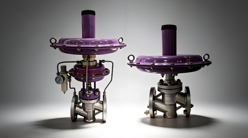
Nitrogen blanketing is a pressure-control method that introduces an inert gas, usually nitrogen, into the vapor space above a stored liquid. The objective is to maintain a specified pressure and gas composition while minimizing the entry of atmospheric air. Nitrogen supply valves, also called tank blanketing valves or padding valves, admit nitrogen when tank pressure falls below the required operating range. Nitrogen venting valves, often called de-blanketing valves or controlled vent valves, release excess vapor when pressure rises above their designated set point.
These valves are commonly installed on tanks containing solvents, fuels, chemical intermediates, pharmaceutical ingredients, and other products sensitive to oxygen, moisture, contamination, or evaporation. Their importance extends beyond pressure regulation: the nitrogen blanket can reduce oxidation, limit the formation of flammable vapor-air mixtures under appropriately designed conditions, and help reduce product losses. Technical guidance from Emerson describes the same operating principle: nitrogen enters when tank pressure decreases, while gas is discharged when pressure rises because of liquid filling or thermal effects.
It is important to distinguish a blanketing system from a complete tank protection system. The supply and venting valves regulate routine operating pressure, whereas pressure/vacuum relief devices and emergency venting equipment protect the tank against pressure or vacuum conditions beyond the normal control range. The final arrangement depends on tank design, product properties, process conditions, applicable codes, and the consequences of equipment failure.
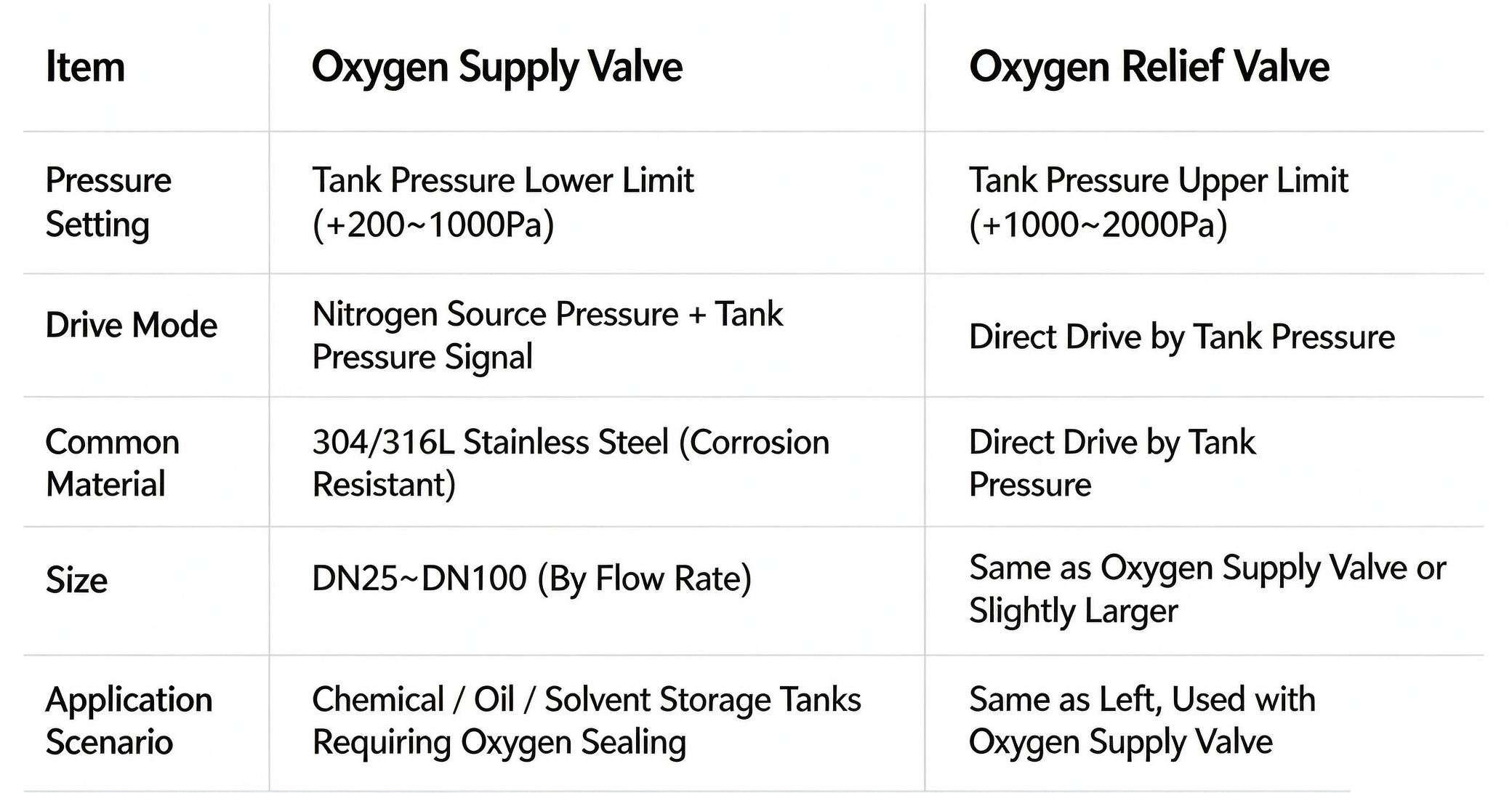
A nitrogen supply valve is usually a low-pressure self-operated regulator. It senses tank pressure through an internal sensing arrangement or an external sensing line and adjusts the nitrogen flow accordingly. When tank pressure drops below its set point, the valve opens to introduce nitrogen. As pressure recovers, the valve throttles or closes to reduce gas consumption and maintain the desired pressure.
The pressure drop can occur for several reasons:
- Liquid is withdrawn from the tank, increasing the vapor-space volume.
- The gas in the vapor space cools and contracts.
- Vapor condenses, reducing the gas-phase volume.
- Minor leakage or process disturbances reduce tank pressure.
- Changes in operating conditions increase the demand for replacement gas.
For example, when a storage tank supplies liquid to a downstream process, the liquid level falls, and the vapor space expands. If nitrogen is not supplied, the tank pressure may decrease, and atmospheric air may enter through openings or other available flow paths. A properly selected blanketing regulator supplies replacement gas to maintain the specified pressure.
A nitrogen venting valve performs the complementary function. When tank pressure rises above its set point, the valve opens or modulates to discharge excess vapor. Once pressure returns to the intended operating range, the valve closes or reduces its opening.
Typical causes of pressure rise include:
- Liquid entering the tank and displacing vapor.
- An increase in vapor temperature caused by ambient heating or process heat.
- Vapor generation, evaporation, or flashing of the incoming liquid.
- Excessive nitrogen supply caused by regulator malfunction or an incorrect setting.
- Changes in downstream vapor recovery system pressure.
In a system designed to recover volatile organic compounds (VOCs), the venting valve may discharge to a closed vapor collection or treatment system rather than directly to the atmosphere. Such an arrangement can help reduce emissions and conserve valuable process vapors. However, the valve must be suitable for the receiving system's backpressure, since downstream pressure can affect its opening characteristics and effective relieving capacity.
The two valves should operate in a coordinated manner rather than continuously opposing each other.
- Normal operation: Tank pressure remains between the supply-valve and venting-valve set points. Both valves are generally closed or nearly closed, depending on their designs and the process conditions.
- Pressure decrease: When tank pressure falls below the supply regulator's set point, the nitrogen supply valve opens and replenishes the vapor space.
- Pressure recovery: As the pressure returns to the target range, the supply valve reduces flow and closes.
- Pressure increase: If pressure rises above the venting valve's set point, the venting valve opens or modulates to discharge excess gas.
- Return to normal: After pressure falls below the venting threshold, the venting valve closes or reduces its opening.
The actual response depends on the valve design, sensing arrangement, available pressure differential, flow demand, and dynamic behavior of the tank. A well-designed system should avoid unnecessary overlap between nitrogen addition and vapor discharge.
The pressure deadband, also called the pressure differential or operating gap, is the difference between the nitrogen supply valve's opening set point and the nitrogen venting valve's opening set point. It creates a pressure range within which neither valve needs to respond actively to routine fluctuations.
Consider the following illustrative settings:
| Parameter | Example setting | Function |
|---|---|---|
| Nitrogen supply valve | 1,000 Pa gauge | Adds nitrogen when pressure falls below its threshold |
| Nitrogen venting valve | 1,500 Pa gauge | Releases vapor when pressure rises above its threshold |
| Nominal set-point difference | 500 Pa | Separates the two control thresholds |
In this example, the nominal deadband is 500 Pa, equivalent to 5 mbar. These figures illustrate the principle; they are not universal recommendations. Actual set points must be selected according to tank allowable pressure, product requirements, valve characteristics, expected pressure fluctuations, and the settings of all other pressure-control and relief devices.
If the two set points are too close, small fluctuations may cause repeated opening and closing. This behavior, often called valve hunting or chatter depending on the mechanism, can accelerate seat wear, increase nitrogen consumption, and destabilize tank pressure. If the difference is too large, the tank may experience an unnecessarily wide pressure range, potentially affecting product protection or exceeding process limits.
A suitable pressure differential should be established from a complete review of the tank's operating envelope.
Key considerations include:
- Tank pressure rating: The normal operating range must remain comfortably within the tank's allowable pressure and vacuum limits.
- Valve accuracy and repeatability: The set-point difference should account for the actual control performance of both valves.
- Process pressure fluctuations: Rapid filling, pumping, temperature changes, and vapor generation can influence pressure response.
- Valve capacity and response time: An undersized valve may allow pressure to move far beyond its set point before adequate flow is established.
- Vapor recovery backpressure: A venting valve connected to a closed system may behave differently from one discharging to a low-pressure destination.
- Other protective devices: Pressure/vacuum vents and emergency relief devices need appropriately coordinated set points.
Technical guidance on inerting and blanketing emphasizes that pressure settings should be separated sufficiently to reduce interaction and rapid cycling between devices. The appropriate separation, however, must be determined for the particular installation rather than copied from an example.
Many stored liquids react with oxygen or are adversely affected by atmospheric moisture. Examples include certain solvents, specialty chemicals, oils, and pharmaceutical intermediates. Introducing nitrogen into the vapor space helps reduce contact between the product and atmospheric air, thereby supporting product stability and storage quality.
A nitrogen blanket can also limit the ingress of airborne contaminants when the tank is operating under positive pressure, and the system is sufficiently tight. Nevertheless, positive pressure alone does not guarantee a specific oxygen concentration. Air may enter through leaks, imperfect seals, maintenance openings, or abnormal operating conditions. Where oxygen concentration is critical, the design may require oxygen monitoring, verified inerting procedures, leak control, and defined operating limits.
Volatile liquids can generate vapor as temperature and pressure change. A suitable nitrogen blanketing and vapor recovery arrangement may reduce uncontrolled vapor release and help preserve product inventory. The actual benefit depends on liquid volatility, tank turnover, temperature, sealing quality, vent configuration, and whether discharged vapor is recovered or treated.
A controlled venting valve can direct vapor toward a closed recovery system, where compatible equipment can collect, process, or return the vapor. This may be particularly valuable for solvent storage and other operations where emissions control and product recovery are important.
It should not be assumed that nitrogen blanketing automatically eliminates evaporation. The system must be designed around the material's vapor pressure and the intended emission-control strategy, and the nitrogen itself can contribute to the volume of gas discharged through the vent.
Nitrogen is commonly used as an inerting gas because it reduces the oxygen concentration in the vapor space. If the oxygen concentration is maintained below the relevant limiting oxidant concentration for the specific fuel, temperature, pressure, and operating conditions, combustion may be prevented within the defined system boundary.
However, nitrogen blanketing should not be treated as an automatic guarantee against fire or explosion. The required oxygen limit depends on the material and process conditions, and a safe design requires a documented basis for the inerting target, nitrogen supply reliability, monitoring requirements, and failure response. The UK Health and Safety Executive identifies inerting as an effective explosion-prevention method for suitable enclosed processes, while emphasizing the need to apply it to the relevant hazard.
Nitrogen also introduces an asphyxiation hazard because it can displace oxygen in surrounding work areas. Vent outlets, relief discharges, maintenance procedures, and confined-space controls must therefore be designed and managed to protect personnel.
Many atmospheric and low-pressure storage tanks have relatively thin shells and roofs. They are not designed to withstand arbitrary internal pressure or vacuum. A severe vacuum can cause shell buckling or roof deformation, while excessive internal pressure can damage the roof, shell, seals, or associated connections.
The nitrogen supply valve helps prevent routine vacuum formation by replacing the volume lost through liquid withdrawal or gas contraction. Nevertheless, it is not a substitute for a correctly sized vacuum-relief device. If nitrogen supply is interrupted, the regulator fails, or demand exceeds its capacity, the tank may still develop a damaging vacuum.
Likewise, the nitrogen venting valve controls routine pressure increases but cannot automatically be assumed to provide sufficient protection during every abnormal or emergency event.
A common design error is to assume that the nitrogen supply and venting valves can replace all tank breathing and relief equipment. Their normal operating functions are different from those of independent protective devices.
| Equipment | Primary purpose | Typical operating role |
|---|---|---|
| Nitrogen supply valve | Maintain a nitrogen blanket | Supplies gas when pressure decreases |
| Nitrogen venting valve | Control excess blanket pressure | Discharges gas when pressure increases |
| Pressure/vacuum relief valve | Protect the tank from excessive pressure or vacuum | Opens at its specified relief threshold |
| Emergency vent or relief device | Address defined emergency pressure scenarios | Provides additional relieving capacity when required |
| Flame arrester, where specified | Mitigate flame propagation through a compatible flow path | Provides a defined protection function under assessed conditions |
| Oxygen analyzer, where required | Monitor oxygen concentration | Supports verification of inerting performance |
The specific equipment combination depends on the tank design and hazard assessment. Pressure/vacuum relief devices should be sized for the required operating and abnormal cases in accordance with the applicable design basis. A blanketing regulator may fail, the nitrogen supply may become unavailable, or process flow may exceed normal expectations. The tank must remain adequately protected when such events occur.
API Standard 2000 addresses normal and emergency venting requirements for atmospheric and low-pressure storage tanks within its scope. The current eighth edition was published in August 2026, replacing the previous edition. ISO 28300 also covers normal and emergency vapor venting requirements for relevant storage tanks. Engineers should confirm the applicable edition, jurisdictional requirements, and project specifications before using either standard for a design.
Tank blanketing valves often operate at very low downstream pressures, even when the nitrogen supply header is at a much higher pressure. The selected regulator must therefore provide the required low-pressure control while handling the available inlet pressure and the expected flow range.
The specified operating pressure should account for the tank's allowable pressure, the desired blanket pressure, the pressure losses in the sensing and connection arrangements, and the interaction with venting and relief devices. A regulator that performs well at one flow rate may not maintain the same accuracy under very low or very high demand.
Suppliers should provide pressure-control performance data, flow-capacity curves, minimum controllable flow, and relevant installation limitations. Where low set points or high flow rates make internal sensing unsuitable, an external sensing line may improve measurement of actual tank pressure, provided that the line is correctly designed and maintained.
The supply valve must deliver enough nitrogen to replace the vapor-space volume created by liquid withdrawal and gas contraction. Its capacity should be checked against the most demanding credible operating case rather than selected solely from the tank's nominal volume.
Important inputs include:
- Maximum liquid withdrawal rate.
- Thermal contraction of the vapor space.
- Tank size and operating temperature.
- Nitrogen supply pressure and its potential variation.
- Pressure losses in the supply line, fittings, and associated equipment.
- The required tank pressure and the regulator's performance at that pressure.
A regulator that is too small may fail to maintain positive pressure during peak demand. Conversely, an oversized regulator may have poor control at low flow rates, potentially causing pressure fluctuations or excessive nitrogen consumption.
Valve body, trim, diaphragm, seals, and gasket materials should be selected according to the service environment. Nitrogen compatibility is only one consideration: the valve may also be exposed to process vapor, condensate, moisture, cleaning chemicals, or corrosive atmospheric conditions.
Stainless steel may be appropriate for some services, but it is not automatically the best choice for every installation. The correct alloy and seal material depend on temperature, pressure, chemical compatibility, cleanliness requirements, and applicable specifications.
For pharmaceutical or sanitary applications, additional requirements may include suitable surface finishes, controlled cleanliness, and material traceability. For hazardous or corrosive services, engineers should review the complete wetted-material list rather than relying on a generic description such as "stainless steel valve."
The venting valve must discharge enough gas to control pressure during the relevant operating scenarios. These scenarios may include liquid filling, vapor generation, thermal expansion, and the maximum credible nitrogen inflow if the supply regulator fails in a way that allows excessive flow.
The required capacity depends on the combined gas load, the permitted pressure rise, gas properties, valve characteristics, and downstream conditions. Where the valve discharges into a vapor recovery header, backpressure must be included in the assessment because it can reduce available differential pressure and change the valve's operating performance.
The valve should not be selected based only on nominal pipe size. Engineers should obtain certified or otherwise appropriate capacity data for the specified gas, set pressure, relieving pressure, and downstream pressure.
The venting arrangement is an important process decision.
Open or atmospheric discharge may be suitable only where the material, emissions, fire and explosion hazards, environmental rules, and site design permit it. It can result in the release of nitrogen and process vapor to the surrounding environment.
Closed vapor recovery directs discharged gas to a collection, treatment, or recovery system. It may reduce VOC emissions and product losses, but introduces potential backpressure, additional piping losses, and interactions with downstream equipment.
Where toxic, flammable, or environmentally harmful vapor is present, the discharge destination should be evaluated as part of the overall process safety and emissions-control design. A venting valve should never be connected to a closed header without confirming that the header can accept the flow and pressure conditions.
Unnecessary leakage through a venting valve can waste nitrogen, increase operating costs, and send excess gas into a vapor recovery system. Leakage through a supply regulator can also lead to continuous nitrogen consumption and elevated tank pressure.
Valve seat materials, closing force, cleanliness, wear, and pressure differential all influence shutoff performance. Procurement specifications should identify the required leakage performance and the test method, rather than using vague terms such as "zero leakage" without a defined acceptance criterion.
Correct sizing requires more than choosing a valve based on tank volume. The engineer must identify the relevant operating cases, calculate gas demand and discharge requirements, and verify that the valves and protective devices can perform under the specified conditions.
Collect the tank's design pressure and vacuum limits, dimensions, operating volume, liquid properties, maximum filling and withdrawal rates, expected temperature range, and vapor-space characteristics. Also identify the nitrogen supply pressure range, the intended operating pressure, the discharge destination, and any requirements for oxygen concentration or vapor recovery.
Nitrogen supply demand generally includes the gas needed to replace liquid removed from the tank and the gas needed to compensate for thermal contraction or other pressure-reducing effects.
Liquid withdrawal is often a major contributor: as liquid leaves, replacement gas is needed to occupy the newly available vapor-space volume. Thermal effects can add to this demand, particularly when the gas space cools or vapor condenses.
The calculation method should follow the applicable engineering standard and project design basis. API Standard 2000 and ISO 28300 provide frameworks for assessing tank venting requirements within their scopes, but the exact calculation method and applicability must be confirmed against the current edition and the tank's service.
Venting demand may arise from liquid filling, thermal expansion, vapor generation, and the release of nitrogen. The design should consider the maximum credible combination of relevant loads, including the effect of an abnormal supply-regulator condition where required by the risk assessment.
A vent valve that is adequate for routine liquid filling may be insufficient if a failed-open nitrogen regulator can supply a much higher gas flow. This is one reason the supply valve's maximum credible flow and failure behavior should be known and considered in the protective-device design.
The required capacity of pressure/vacuum relief devices must be evaluated separately from the routine control valves. The design should address the relevant normal, abnormal, and emergency scenarios, including loss of nitrogen supply, regulator malfunction, blocked or restricted piping, and fire exposure where applicable.
The final design should not assume that the blanketing regulator will always function correctly or that the venting valve will always be available. Protective devices must be sized and installed to meet the applicable tank protection requirements.
After preliminary sizing, check the supply line, sensing line, valve capacity, pressure losses, vent piping, downstream backpressure, and interactions among all pressure-control and relief devices. A system-level review is essential because individually suitable valves may perform poorly when installed together with unsuitable piping or conflicting set points.
Install the valves in accordance with the manufacturer's instructions and the approved piping and instrumentation diagram. The pressure-sensing point should represent actual tank vapor-space pressure and should not be unduly affected by pressure losses, liquid accumulation, or local turbulence.
External sensing lines, where used, should be routed to reduce the risk of blockage, leakage, condensation-related problems, or accidental isolation. Any isolation valves in sensing arrangements should be managed so that the regulator cannot unknowingly operate without a valid pressure signal.
Supply piping should provide sufficient nitrogen flow without excessive pressure loss. Vent piping should be designed for the expected gas flow and discharge conditions, with consideration given to backpressure, drainage, condensation, and access for inspection.
Where a closed vapor recovery system is used, its operating pressure and capacity should be compatible with the venting valve. A downstream restriction can undermine pressure control even if the valve itself is correctly sized.
Before commissioning, verify valve orientation, material specifications, line cleanliness, sensing connections, instrument ranges, and the condition of relevant protective devices. Set-point adjustments should be performed under controlled conditions using appropriate pressure measurement equipment and the manufacturer's procedure.
The commissioning record should include the approved set points, test results, observed opening and closing behavior, leakage checks where specified, and confirmation that pressure/vacuum protection is available. Changes to one valve's setting should trigger a review of the other devices' settings and the tank's allowable operating envelope.
| Symptom | Possible causes | Recommended checks |
|---|---|---|
| Nitrogen consumption is unusually high | Supply regulator leakage, incorrect set points, vent valve leakage, tank leaks | Check shutoff performance, pressure settings, and system tightness |
| Supply and vent valves operate frequently | Deadband too narrow, unstable pressure signal, poor sizing, excessive process fluctuations | Review set-point separation, sensing lines, and valve capacity |
| Tank pressure remains too low | Insufficient nitrogen supply, blocked line, low header pressure, undersized valve | Verify supply pressure, flow capacity, and sensing arrangements |
| Tank pressure rises excessively | Vent restriction, undersized vent valve, excessive vapor generation, supply regulator failure | Check vent capacity, downstream backpressure, and regulator condition |
| Pressure fluctuates rapidly | Valve hunting, poor sensing arrangement, excessive friction or restriction, incompatible settings | Inspect sensing connections and assess the dynamic response |
| Product quality deteriorates | Air ingress, inadequate inerting, leakage, unsuitable storage conditions | Verify oxygen-control objectives, system integrity, and product requirements |
These symptoms are diagnostic clues rather than proof of a specific fault. Troubleshooting should begin with safe operating procedures and a review of the actual pressure trend, valve position where available, and process conditions. Do not isolate or disable a required protective device simply to stop cycling or reduce nitrogen consumption.
Regular maintenance helps preserve control accuracy and reduces the risk of unnoticed nitrogen leakage or inadequate venting capacity. Inspection frequency should be determined by service severity, manufacturer recommendations, site procedures, and the consequences of failure.
A practical maintenance program may include the following checks:
- Inspect external condition: Look for corrosion, mechanical damage, loose connections, and signs of leakage.
- Verify pressure settings: Confirm that supply and venting set points remain within approved limits and maintain the required separation.
- Check sensing arrangements: Inspect sensing lines, connections, and pressure taps for leakage, blockage, or unintended isolation.
- Assess valve movement: Investigate sticking, delayed response, abnormal noise, or repeated cycling.
- Test shutoff performance: Use the specified procedure and acceptance criteria to assess seat leakage and regulator closure.
- Review vent piping: Check for restrictions, condensate accumulation, corrosion, and unexpected backpressure.
- Inspect independent protection: Confirm that pressure/vacuum relief and emergency venting devices remain available and maintained under the relevant inspection program.
- Document findings: Record set points, repairs, test results, replacement parts, and any changes to the operating envelope.
Maintenance work should be carried out by qualified personnel following isolation, depressurization, gas-testing, and other applicable safety procedures. Nitrogen can create an oxygen-deficient atmosphere, and tank vapor may be toxic or flammable. Opening a tank or removing a valve should therefore be treated as a controlled maintenance activity rather than a routine mechanical task.
Refineries and petrochemical plants store fuels, solvents, intermediates, and other volatile liquids that may require controlled vapor-space conditions. Nitrogen blanketing can help reduce air ingress and support vapor recovery, while correctly sized venting and relief devices protect the tank under the defined operating conditions.
Chemical storage systems may contain oxygen-sensitive, moisture-sensitive, flammable, or corrosive materials. Valve materials, seals, control accuracy, and vent destinations must be selected according to the stored chemical and the consequences of vapor release. In some applications, oxygen concentration monitoring or additional inerting controls may be necessary.
Product purity and batch consistency can make nitrogen blanketing important in pharmaceutical and fine chemical operations. The system may require documented materials, clean construction, defined cleaning practices, and traceable commissioning records. The exact hygienic requirements depend on the process and the relevant quality system.
Certain oils and other products can deteriorate through oxidation or exposure to moisture. Nitrogen blanketing may help preserve product quality, provided that the gas supply meets the required quality specifications and the tank system is designed to maintain the intended atmosphere.
Tank nitrogen blanketing and venting design should be based on the applicable laws, standards, project specifications, and site risk assessment. API Standard 2000 and ISO 28300 are relevant references for normal and emergency venting of storage tanks within their respective scopes. NFPA 69 addresses explosion-prevention systems, including inerting applications where applicable. The applicable edition and jurisdictional requirements should be verified for each project.
A complete design package should normally identify:
- Tank design pressure and vacuum limits.
- Normal operating pressure range and allowable deviations.
- Nitrogen supply and venting valve set points.
- Valve capacity calculations and relevant flow conditions.
- Maximum credible nitrogen flow, including relevant failure cases.
- Pressure/vacuum relief and emergency venting requirements.
- Vent discharge destination and backpressure assumptions.
- Materials, seals, connections, and inspection requirements.
- Oxygen-control objectives and monitoring requirements, where applicable.
- Commissioning, testing, and maintenance procedures.
The purpose of this documentation is to make the design assumptions explicit and ensure that control and protection functions remain coordinated throughout the equipment lifecycle.
Purchasing teams should provide a technical specification that describes both the operating requirements and the required performance. A general description such as "nitrogen valve for a storage tank" does not provide enough information for a reliable selection.
A procurement checklist should cover:
- Service: Nitrogen supply, controlled venting, or another defined function.
- Design and operating pressure: Including normal pressure, set pressure, and allowable tank limits.
- Flow capacity: Required minimum and maximum flow under stated inlet and outlet conditions.
- Connection details: Nominal size, end connection, piping arrangement, and applicable dimensional standards.
- Materials: Body, trim, diaphragm, seals, and gaskets compatible with the service.
- Control performance: Set-point accuracy, repeatability, stability, and required shutoff performance.
- Discharge conditions: Atmospheric discharge or closed recovery, including expected backpressure.
- Documentation: Data sheets, capacity curves, material certificates where required, test records, and maintenance instructions.
- System compatibility: Coordination with the companion valve and independent pressure/vacuum protection devices.
A qualified supplier should be able to explain the proposed valve's operating principle, capacity at the specified conditions, limitations, and maintenance requirements. The buyer should evaluate the complete technical offer rather than selecting equipment on nominal size or initial purchase price alone.
Nitrogen supply valves and nitrogen venting valves are complementary components of a storage tank blanketing system. The supply valve replaces gas when tank pressure decreases, while the venting valve releases excess gas when pressure increases. By maintaining a suitable pressure band, they help protect product quality, limit air ingress, support emissions management, and improve routine operating stability.
Reliable performance depends on more than the two valves themselves. Correct capacity calculations, compatible materials, suitable sensing arrangements, a properly selected pressure deadband, and coordinated discharge piping are all essential. Most importantly, routine blanketing control must be distinguished from independent pressure and vacuum protection. A complete engineering design considers normal operation, credible equipment failures, emergency venting requirements, and personnel hazards so that the tank and its contents remain protected under the specified conditions.

BALTIC VALVE CO., LTD supplies superior quality industrial valves covering ball valves, globe valves, gate valves, check valves, plug valves, butterfly valves, marine valves, forging steel valve, filter, etc.

Nitrogen Blanketing and Venting Valves Explained
Oct 25, 2026

Ventilation Butterfly Valves: A Practical Guide
Oct 18, 2026

Valve Reliability: Why It Beats Low Prices
Oct 10, 2026
Baltic Valve Co., Ltd.
Add: Baltic Valve Park, Siming, Xiamen, China.
Tel: +86 592 8266 140
Fax: +86 592 8266 440
Mail: [email protected]
Website: https://www.baltic-valve.com
Copyright © 2017-2026 Baltic Valve Co., Ltd. All rights reserved. Privacy Policy | Terms of Service
Website Design & Support: jeawin.com