The Improvement in the Hard-seal Trunnion Ball Valve for the Coal Chemical Industry (Part Two)
1.2 Design of the connecting structure of the valve stem and sphere
There are various structures for connecting the valve stem and sphere. To adapt to harsh working conditions such as high temperatures and high pressure and multiphase flows in the coal chemical industry, we choose a pin connection concentric structure for the hard-sealed ball valve in the coal chemical industry. Various connection methods are as follows.
1.2.1 Square or rectangular grooves
The distribution of the specific pressure of the valve stem and sphere on the contact surface is not uniform by adopting this connection. The distribution of the specific pressure of the ball's connecting groove is shown in Figure 5. After the ball valve has been opened and closed for some time, the connection and contact parts of the ball and the valve stem will be worn to different degrees, and the original tight fit becomes a clearance fit, which will cause extremely uneven extrusion stress on the contact surface of the valve stem and sphere. The partial squeeze deteriorates from elastic deformation to plastic deformation. The coating near the connecting surface of the sphere will crack and fall. In severe cases, the cracking of the coating will extend to the sealing surface and cause the valve's sealing to fail. The squeezing deformation of the sphere is shown in Figure 6.
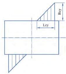
Figure 5 The distribution of the specific pressure of the sphere's connecting groove
Plate note that Lzy is the extrusion length and Bzy is the extrusion stress.
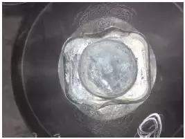
Figure 6 Squeeze deformation of the sphere
1.2.2 Keys
The key is easy to loosen in the shaft groove. The stress concentration at the end of the key groove on the shaft is great, and the key groove needs to be processed on a milling machine; the processing technology is more complicated than other connections.
1.2.3 Pins
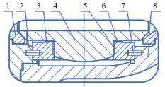
The concentric structure of the valve stem and sphere pin prevents the center of the sphere and valve stem from being in a straight line due to the clearance fit, and the processing technology is also simple. The distribution of the contact surface's specific pressure of this structure is uniform, and the approximate extrusion stress and shear stress of the valve stem's connection part are smaller than the traditional rectangular connection. The connection of the sphere and valve stem pin is shown in Figure 7. This connection has the advantages of the sphere and valve stem being integrally connected for the traditional slag lock valve. The operating torque is stable and the transmission torque is great enough. At the same time, it avoids the inherent defects of the sphere and valve stem being integrally connected. When the sphere and valve stem are integrally designed, the valve stem will have a tendency of upward displacement under the action of the medium's force, which will cause uneven distribution of specific pressure on the contact circle of the sphere and valve seat, and uneven wear in the valve's closing process, eventually causing the valve to leak.
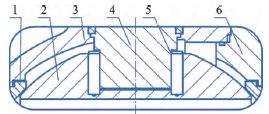
Figure 7 The connection of the sphere and stem pin
There are various structures for connecting the valve stem and sphere. To adapt to harsh working conditions such as high temperatures and high pressure and multiphase flows in the coal chemical industry, we choose a pin connection concentric structure for the hard-sealed ball valve in the coal chemical industry. Various connection methods are as follows.
1.2.1 Square or rectangular grooves
The distribution of the specific pressure of the valve stem and sphere on the contact surface is not uniform by adopting this connection. The distribution of the specific pressure of the ball's connecting groove is shown in Figure 5. After the ball valve has been opened and closed for some time, the connection and contact parts of the ball and the valve stem will be worn to different degrees, and the original tight fit becomes a clearance fit, which will cause extremely uneven extrusion stress on the contact surface of the valve stem and sphere. The partial squeeze deteriorates from elastic deformation to plastic deformation. The coating near the connecting surface of the sphere will crack and fall. In severe cases, the cracking of the coating will extend to the sealing surface and cause the valve's sealing to fail. The squeezing deformation of the sphere is shown in Figure 6.
Figure 5 The distribution of the specific pressure of the sphere's connecting groove
Plate note that Lzy is the extrusion length and Bzy is the extrusion stress.
Figure 6 Squeeze deformation of the sphere
1.2.2 Keys
The key is easy to loosen in the shaft groove. The stress concentration at the end of the key groove on the shaft is great, and the key groove needs to be processed on a milling machine; the processing technology is more complicated than other connections.
1.2.3 Pins
The concentric structure of the valve stem and sphere pin prevents the center of the sphere and valve stem from being in a straight line due to the clearance fit, and the processing technology is also simple. The distribution of the contact surface's specific pressure of this structure is uniform, and the approximate extrusion stress and shear stress of the valve stem's connection part are smaller than the traditional rectangular connection. The connection of the sphere and valve stem pin is shown in Figure 7. This connection has the advantages of the sphere and valve stem being integrally connected for the traditional slag lock valve. The operating torque is stable and the transmission torque is great enough. At the same time, it avoids the inherent defects of the sphere and valve stem being integrally connected. When the sphere and valve stem are integrally designed, the valve stem will have a tendency of upward displacement under the action of the medium's force, which will cause uneven distribution of specific pressure on the contact circle of the sphere and valve seat, and uneven wear in the valve's closing process, eventually causing the valve to leak.
Figure 7 The connection of the sphere and stem pin
1. Valve seats 2. Spheres 3. Main valve bodies 4. Valve stems 5. Drive pins 6. Auxiliary valve bodies
1.3 The sphere adopting a shaft-type fixed structure
The upper and lower pivots support the fixed sphere to ensure accurate positioning of the sphere. The sphere does not move in the axial direction of the valve body under the action of the medium's pressure; the structure is simple and the reliability is good. The lower pivot, as the pressure-bearing part at the bottom of the valve, is also the fixing and installation part of the sealing gasket and the spring adjustment mechanism at the lower part of the valve body.
At the same time, a built-in spring adjustment mechanism is installed on the lower pivot, and a spring is provided under the cushion block. The spring can not only bear the weight of the sphere, but also change the compression of the spring to establish a good matched relationship between the valve seat and the center of the sphere's sealing pair by adjusting radial distance between the center of the sphere and the center line of the valve seat channel, improve the sealing performance of the valve, and release the static electricity generated by the sphere due to various reasons. This structure has obtained a utility model patent authorized by the National Intellectual Property Office and is applied to a project with good performance.
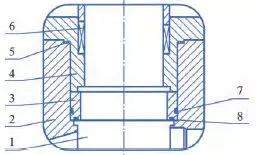
In addition, in coal chemical production, most of the media contains a lot of solid particles. These small particles entering the bearing and pivot will wear the bearing and pivot surface, forming scratches, reducing the service life of the bearing, and even causing the valve to be blocked due to accumulation. Therefore, a graphite dust-proof ring is installed to prevent damage to the pivot and bearing by the medium particles. The structure of the lower pivot of the sphere is shown in Figure 8.
1.3 The sphere adopting a shaft-type fixed structure
The upper and lower pivots support the fixed sphere to ensure accurate positioning of the sphere. The sphere does not move in the axial direction of the valve body under the action of the medium's pressure; the structure is simple and the reliability is good. The lower pivot, as the pressure-bearing part at the bottom of the valve, is also the fixing and installation part of the sealing gasket and the spring adjustment mechanism at the lower part of the valve body.
At the same time, a built-in spring adjustment mechanism is installed on the lower pivot, and a spring is provided under the cushion block. The spring can not only bear the weight of the sphere, but also change the compression of the spring to establish a good matched relationship between the valve seat and the center of the sphere's sealing pair by adjusting radial distance between the center of the sphere and the center line of the valve seat channel, improve the sealing performance of the valve, and release the static electricity generated by the sphere due to various reasons. This structure has obtained a utility model patent authorized by the National Intellectual Property Office and is applied to a project with good performance.
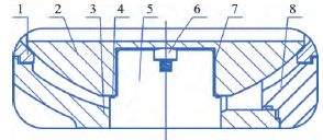
In addition, in coal chemical production, most of the media contains a lot of solid particles. These small particles entering the bearing and pivot will wear the bearing and pivot surface, forming scratches, reducing the service life of the bearing, and even causing the valve to be blocked due to accumulation. Therefore, a graphite dust-proof ring is installed to prevent damage to the pivot and bearing by the medium particles. The structure of the lower pivot of the sphere is shown in Figure 8.
1. Valve seats 2. Spheres 3. Main valve bodies 4. Dust-proof rings 5. Pivots 6. Cushion blocks 7. Bearings 8. Auxiliary valve bodies
Figure 8 Lower pivot structure of the sphere
Figure 8 Lower pivot structure of the sphere
There are also many spheres of trunnion ball valves that adopt the support plate structure to optimize the force of the valve stem, such as pipeline ball valves and oxygen dedicated ball valves. However, for the working condition of the coal chemical industry, support plates with complicated structure and poor fluidity of the medium easily cause a lot of solid particles to stick to the inside of the valve cavity to form scaling and block the valve cavity, which is not applicable. The structure of the sphere support plate is shown in Figure 9.
1. Valve seats 2. Auxiliary valve bodies 3. Support plates 4. Spheres 5. Bearings 6. Friction reducing pads 7. Pins 8. Main valve bodies
Figure 9 The structure of the sphere's support plate
1.4 The structure of the bearing
The inner surface of the bearing matched with the sphere, valve stem and valve body is hardened by spraying cemented carbide or nitriding treatment, which greatly improves the wear resistance. Good hardness and wear resistance can still be obtained at high temperatures, which can ensure that the valve will not seized when it is opened and closed for a long time. At the same time, the valve's operating torque can be effectively reduced, the sealing performance of the packing enhanced, the valve stem guided, and the wear of the packing caused by the radial movement of the valve stem eliminated. To prevent particles from entering and protect the valve stem and packing box, dust-proof rings I and II are designed and installed on the lower end and outside of the bearing to protect the valve stem and packing box. The bearing structure is shown in Figure 10.
1. Valve stems 2. Valve bodies 3. Bearings 4. Packing boxes 5. Gaskets 6. Packing 7. Dust-proof ring I 8. Dust-proof ring II
Figure 10 The structure of the bearing
2. Conclusion
With the development of technology, the application fields of metal hard-sealed and wear-resistant ball valves will be more extensive. Through the above analysis of the four structures of hard-sealed ball valves, and the actual working conditions of the coal chemical industry, these structures are optimized, which is conducive to improving the performance and service life of the valve. It is hoped that the arguments in this article can provide a certain reference for the construction of the valve industry and play a positive role in improving the level of valve design in China.
Previous: The Improvement in the Hard-seal Trunnion Ball Valve for the Coal Chemical Industry (Part One)
Next: Top Entry Metal Seated Butterfly Valves
Next: Top Entry Metal Seated Butterfly Valves

Baltic Valve
BALTIC VALVE CO., LTD supplies superior quality industrial valves covering ball valves, globe valves, gate valves, check valves, plug valves, butterfly valves, marine valves, forging steel valve, filter, etc.
Stay Connected
Latest News

DBB Ball Valves Available from Workshop Stock
Jun 30, 2026


High Pressure Globe Valve PN320, Forged Material
Apr 13, 2026
Contact Us
Baltic Valve Co., Ltd.
Add: Baltic Valve Park, Siming, Xiamen, China.
Tel: +86 592 8266 140
Fax: +86 592 8266 440
Mail: [email protected]
Website: https://www.baltic-valve.com
Copyright © 2017-2026 Baltic Valve Co., Ltd. All rights reserved. Privacy Policy | Terms of Service
Website Design & Support: jeawin.com