The Improvement in the Hard-seal Trunnion Ball Valve for the Coal Chemical Industry (Part One)
Abstract
The optimization and improvement in the design of the partial structure of the hard-seal trunnion ball valve for the coal chemical industry is introduced, involving the static sealing structure of the valve seat and valve body, connection structure of the valve stem and sphere, fixed structure of the sphere pivot and upper and lower bearing structures. The improvement improves the performance and service life of the valve.
As one of China's main fossil energy sources, coal has a comprehensive and diverse industrial structure derived from it. The coal chemical industry has made great contributions to the sustainable development and strategic needs of China's national economy all the time.
After years of development in the coal chemical industry, the output value of production capacity has reached a certain scale. The traditional coal chemical industry will no longer expand, and the industrial pattern of the new coal chemical industry has basically formed. At present, China's coal chemical industry is in a downturn of oversupply and overcapacity due to the continued decline of the price of international crude oil, the increasing domestic awareness of energy conservation, emission reduction and environmental protection, and the slowdown of economic growth. In this context, higher requirements are put forward for the reliable operation of coal chemical plants, and more technological upgrades, inventions and innovations of new technologies and new products are required on the basis of the original scale to improve the high-quality and efficient use of coal, improve the economic efficiency and product competitiveness of the overall coal chemical industry, and avoid redundant construction without technology.
As an indispensable device in coal chemical plants, higher technical requirements and independent development capabilities should be put forward for a ball valve. We can learn from foreign advanced technology, and then deepen and optimize it. Carry out technological innovation. Develop new products and reduce valve design and manufacturing costs; strictly control the valve's quality; increase the valve's added value, and gradually replace imported valves, realizing valves being made in China.
1. Structural analyses and improvements
1.1 The sealing structure of the valve seat
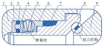
The structure of the hard sealing pair of the ball valve is shown in Figure 1. A double valve seat structure has double block and bleed functions, that is, a DBB function. It also has a design of self relief and self cleaning. The valve seat and sphere are matched and ground, and belt shaped sealing can achieve the purpose of zero leakage. Multiple surface coatings are available, dynamic compensation, pressure difference balance and functions of anti-lock failures are designed for springs. A slag-proof structure is designed for the valve seat, which can effectively prevent the coal powder or coal slag entering the valve seat’s sealing cavity from the valve cavity and flow channel.
The optimization and improvement in the design of the partial structure of the hard-seal trunnion ball valve for the coal chemical industry is introduced, involving the static sealing structure of the valve seat and valve body, connection structure of the valve stem and sphere, fixed structure of the sphere pivot and upper and lower bearing structures. The improvement improves the performance and service life of the valve.
As one of China's main fossil energy sources, coal has a comprehensive and diverse industrial structure derived from it. The coal chemical industry has made great contributions to the sustainable development and strategic needs of China's national economy all the time.
After years of development in the coal chemical industry, the output value of production capacity has reached a certain scale. The traditional coal chemical industry will no longer expand, and the industrial pattern of the new coal chemical industry has basically formed. At present, China's coal chemical industry is in a downturn of oversupply and overcapacity due to the continued decline of the price of international crude oil, the increasing domestic awareness of energy conservation, emission reduction and environmental protection, and the slowdown of economic growth. In this context, higher requirements are put forward for the reliable operation of coal chemical plants, and more technological upgrades, inventions and innovations of new technologies and new products are required on the basis of the original scale to improve the high-quality and efficient use of coal, improve the economic efficiency and product competitiveness of the overall coal chemical industry, and avoid redundant construction without technology.
As an indispensable device in coal chemical plants, higher technical requirements and independent development capabilities should be put forward for a ball valve. We can learn from foreign advanced technology, and then deepen and optimize it. Carry out technological innovation. Develop new products and reduce valve design and manufacturing costs; strictly control the valve's quality; increase the valve's added value, and gradually replace imported valves, realizing valves being made in China.
1. Structural analyses and improvements
1.1 The sealing structure of the valve seat
The structure of the hard sealing pair of the ball valve is shown in Figure 1. A double valve seat structure has double block and bleed functions, that is, a DBB function. It also has a design of self relief and self cleaning. The valve seat and sphere are matched and ground, and belt shaped sealing can achieve the purpose of zero leakage. Multiple surface coatings are available, dynamic compensation, pressure difference balance and functions of anti-lock failures are designed for springs. A slag-proof structure is designed for the valve seat, which can effectively prevent the coal powder or coal slag entering the valve seat’s sealing cavity from the valve cavity and flow channel.
1. Valve bodies 2. Concave compression rings 3. Dust-proof graphite rings 4. Convex compression rings 5. Disc springs 6. Compression rings 7. Graphite rings 8. Valve seats 9. Spheres
Figure 1 The sealing structure of the valve seat
Compared with the combined valve seat structure of ordinary ball valves, the structural design of this valve seat combines the special working conditions of the coal chemical industry and targeted optimization design is carried out. The integral valve seat is adopted, and the graphite ring, compression ring, disc spring, convex compression ring, dustproof graphite ring, and concave compression ring are hidden inside the valve seat. Its advantage is that it not only ensures the original function of the valve seat, but also reduces the leakage of the medium when it passed through the static sealing surface, avoiding the scouring of other parts by the particle medium and simplifying the dust-proof structure of the spring cavity. Meanwhile, the overall sealing structure is more stable. The valve seat channel adopts a streamlined design, which makes the fluid resistance smaller, eliminates structural dead ends, and reduces the accumulation and scaling of media. It is especially suitable for two-phase fluid media mixed with hard particles.
The valve seat's pre-tightening force is provided by a disc spring. No matter how the temperature and pressure change, it always gives a thrust to the valve seat, which can not only ensure the sealing performance of the valve under low-pressure conditions, but also repair the wear of the sealing surface, making sure the leakage of the valve seat meets the requirements. The number of disc springs of spring cavities can be flexibly designed according to the valve's working conditions: ① They can be used alone. ② They can be superimposed. The spring's pretightening force is unchanged, but can provide greater spring deformation to compensate for wear of the sealing surface due to machining errors and long-term operation under high temperatures and high pressure, ensuring that the sphere and sealing surface are always matched. ③The superposition is adopted, and the spring deformation is unchanged, which can provide greater spring pretightening force and make up for the shortcomings of insufficient pre-tightening force of the spring after long-term use. The combined structure of the spring cavity is shown in Figure 2.
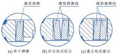
Figure 2 The combined structure of the spring cavity
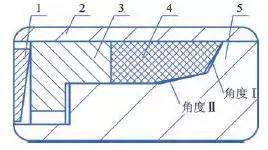
A molded graphite ring made from flexible graphite is provided on the valve seat. The graphite ring structure is a static seal, which has a big contact area with the valve body. The friction and wear problems are more prominent in a high-pressure environment. Through the analysis of the graphite ring and mechanical analysis of the compression by the valve seat and disc spring, use the relevant theories of elastic mechanics to establish the calculation model of the force distribution and deformation distribution of the graphite ring, and obtain a conclusion of reasonable distribution of axial pressure and radial pressure of the conical contact surface and its uniformity increasing with the increase of cone angles. Therefore, the graphite ring is designed with two different angles of conical surface angle I and angle II. This design can meet the progressive increase of the axial and radial pressure distribution of the graphite ring. The closer it is to the sealing point, the greater the specific pressure becomes. A difference of 1° to 2° at the angle of the valve seat enhances the automatic compensation function of the graphite ring radial seal. The structure of the graphite ring of the valve seat is shown in Figure 3.
Compared with the combined valve seat structure of ordinary ball valves, the structural design of this valve seat combines the special working conditions of the coal chemical industry and targeted optimization design is carried out. The integral valve seat is adopted, and the graphite ring, compression ring, disc spring, convex compression ring, dustproof graphite ring, and concave compression ring are hidden inside the valve seat. Its advantage is that it not only ensures the original function of the valve seat, but also reduces the leakage of the medium when it passed through the static sealing surface, avoiding the scouring of other parts by the particle medium and simplifying the dust-proof structure of the spring cavity. Meanwhile, the overall sealing structure is more stable. The valve seat channel adopts a streamlined design, which makes the fluid resistance smaller, eliminates structural dead ends, and reduces the accumulation and scaling of media. It is especially suitable for two-phase fluid media mixed with hard particles.
The valve seat's pre-tightening force is provided by a disc spring. No matter how the temperature and pressure change, it always gives a thrust to the valve seat, which can not only ensure the sealing performance of the valve under low-pressure conditions, but also repair the wear of the sealing surface, making sure the leakage of the valve seat meets the requirements. The number of disc springs of spring cavities can be flexibly designed according to the valve's working conditions: ① They can be used alone. ② They can be superimposed. The spring's pretightening force is unchanged, but can provide greater spring deformation to compensate for wear of the sealing surface due to machining errors and long-term operation under high temperatures and high pressure, ensuring that the sphere and sealing surface are always matched. ③The superposition is adopted, and the spring deformation is unchanged, which can provide greater spring pretightening force and make up for the shortcomings of insufficient pre-tightening force of the spring after long-term use. The combined structure of the spring cavity is shown in Figure 2.
Figure 2 The combined structure of the spring cavity
A molded graphite ring made from flexible graphite is provided on the valve seat. The graphite ring structure is a static seal, which has a big contact area with the valve body. The friction and wear problems are more prominent in a high-pressure environment. Through the analysis of the graphite ring and mechanical analysis of the compression by the valve seat and disc spring, use the relevant theories of elastic mechanics to establish the calculation model of the force distribution and deformation distribution of the graphite ring, and obtain a conclusion of reasonable distribution of axial pressure and radial pressure of the conical contact surface and its uniformity increasing with the increase of cone angles. Therefore, the graphite ring is designed with two different angles of conical surface angle I and angle II. This design can meet the progressive increase of the axial and radial pressure distribution of the graphite ring. The closer it is to the sealing point, the greater the specific pressure becomes. A difference of 1° to 2° at the angle of the valve seat enhances the automatic compensation function of the graphite ring radial seal. The structure of the graphite ring of the valve seat is shown in Figure 3.
1. Disc springs 2. Valve bodies 3. Compression rings 4. Graphite rings 5. Valve seats
Figure 3 The graphite ring structure of the valve seat
Figure 3 The graphite ring structure of the valve seat
The conical structure also reduces the maximum pressing force required for the graphite ring and wear of the graphite ring, and extends the working life. At the same time, it is easier to install and replace because of the conical structure.
To prevent solid particles from entering the back sealing area of the valve seat and affecting the sealing performance of the valve, in addition to adopting the scraper structure design of the valve seat and scratching the sealing surface of the sphere in the opening or closing process, the anti particle valve seat design is also adopted. The back of the seat is sealed with a double-layer dust-proof graphite ring with a concave and convex compression ring structure, which prevents the particulate medium from scaling and blocking after entering the spring cavity under the pretightening force of the spring, causing the spring to fail. The joint between the dustproof graphite ring and concave compression ring is designed as a tapered surface with a certain angle, which can realize the self-sealing function. While increasing the sealing contact area, it is also subjected to the thrust of the disc spring to form an oblique extrusion force. The greater the pressure is, the better the self-sealing effect becomes. The dust-proof structure of the valve seat is shown in Figure 4.
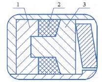
1. Concave compression rings 2. Dustproof graphite rings 3. Convex compression rings
Figure 4 The Dust-proof structure of the valve seat
Previous: Main Factors Affecting the Sealing of the Valve
Next: The Improvement in the Hard-seal Trunnion Ball Valve for the Coal Chemical Industry (Part Two)
Next: The Improvement in the Hard-seal Trunnion Ball Valve for the Coal Chemical Industry (Part Two)

Baltic Valve
BALTIC VALVE CO., LTD supplies superior quality industrial valves covering ball valves, globe valves, gate valves, check valves, plug valves, butterfly valves, marine valves, forging steel valve, filter, etc.
Stay Connected
Latest News


High Pressure Globe Valve PN320, Forged Material
Apr 13, 2026

Big Size of EN Gate Valve for Big Project
Dec 15, 2025
Contact Us
Baltic Valve Co., Ltd.
Add: Baltic Valve Park, Siming, Xiamen, China.
Tel: +86 592 8266 140
Fax: +86 592 8266 440
Mail: [email protected]
Website: https://www.baltic-valve.com
Copyright © 2017-2026 Baltic Valve Co., Ltd. All rights reserved. Privacy Policy | Terms of Service
Website Design & Support: jeawin.com