- November 17, 2026
Can a pneumatic valve continue operating when the electrical power supply is interrupted? In many cases, yes—but only if its compressed-air supply remains available and its control system is designed to support operation without electrical power. If both electricity and instrument air are lost, the valve's response depends on whether it has a spring-return actuator, an air reservoir, a fail-safe control circuit, or a mechanical override.
Unlike electric actuators, which use an electric motor as their primary driving force, pneumatic actuators use compressed air to generate mechanical movement. Electricity is commonly required for accessories such as solenoid valves, electro-pneumatic positioners, sensors, and control systems, rather than for generating the actuator's main operating force. This distinction gives pneumatic valves certain advantages during power interruptions.
However, the ability to operate during an outage should never be assumed simply because a valve is pneumatically actuated. Engineers must distinguish between loss of electrical power, loss of compressed-air supply, and the simultaneous loss of both. They must also determine whether the required response is to open, close, remain in the last position, or move to another predetermined safe position.
Understanding these differences is essential when selecting pneumatic valves for power plants, chemical facilities, oil and gas pipelines, water treatment systems, and other industrial installations where unexpected interruptions may affect process safety and operational continuity.
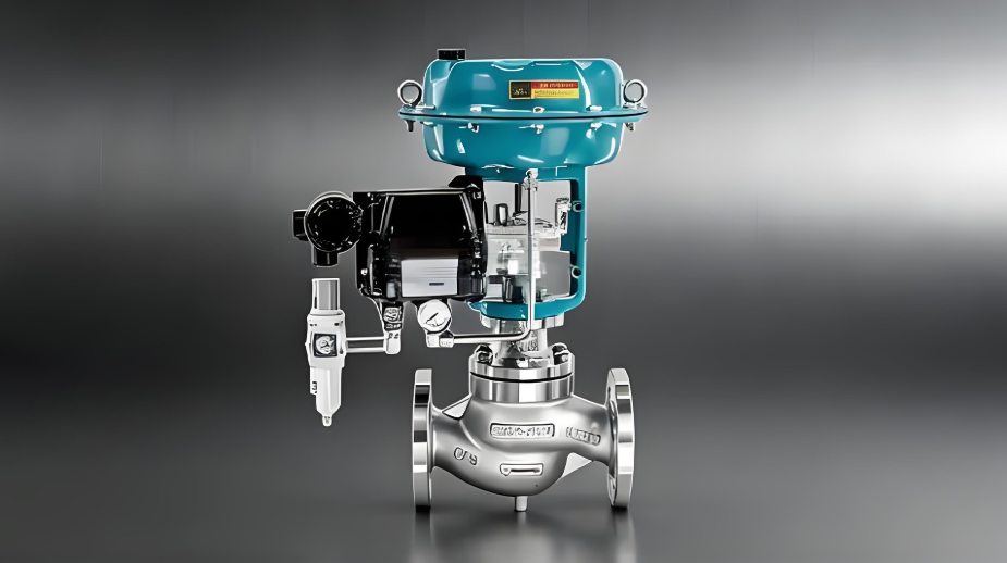
A pneumatic valve assembly generally consists of a valve body, pneumatic actuator, air supply system, and one or more control accessories. These components work together to convert compressed-air energy into mechanical movement that opens, closes, or regulates the valve.
Compressed air is the primary energy source for a pneumatic actuator. When air enters the actuator chamber, its pressure acts on a diaphragm, piston, or vane, producing linear or rotary movement. This movement is transferred to the valve stem or shaft, changing the position of the internal closure element.
Depending on the valve design, pneumatic actuators can operate:
- Gate valves and globe valves through linear movement.
- Ball valves through quarter-turn rotary movement.
- Butterfly valves through quarter-turn rotary movement.
- Plug valves through rotary movement.
- Specialized control valves through continuous positioning.
The actuator's output force or torque must be sufficient to overcome the valve's operating resistance under the specified pressure and temperature conditions.
For example, a pneumatic ball valve requires sufficient torque to rotate the ball against seat friction and the pressure differential across the valve. A pneumatic globe control valve requires sufficient thrust to move its plug and stem against process forces and packing friction.
One of the most important characteristics of pneumatic valves is the separation between their driving energy and their control signals.
The main components have different functions:
| Component | Main Function | Typical Energy Source |
|---|---|---|
| Pneumatic actuator | Generates valve-opening and closing movement | Compressed air |
| Solenoid valve | Directs compressed air into or out of the actuator | Electricity and compressed air |
| Electro-pneumatic positioner | Converts an electrical control signal into pneumatic output | Electricity and compressed air |
| Pneumatic positioner | Controls actuator pressure based on a pneumatic signal | Compressed air |
| Limit switch | Indicates whether the valve is open or closed | Electrical power or passive mechanical switching |
| Air filter regulator | Filters and regulates the instrument-air supply | Compressed air |
| Mechanical handwheel | Provides manual mechanical operation | Human input |
| Air reservoir | Stores compressed air for emergency operation | Previously stored compressed air |
The actuator can therefore have sufficient mechanical energy to move the valve even when the electrical control system is unavailable. However, it still needs a suitable mechanism to direct or release that compressed air.
This distinction explains why some pneumatic valves can continue operating during a power outage while others simply stop responding to remote commands.
A power outage does not necessarily mean that the pneumatic actuator loses its driving energy. If the instrument-air header remains pressurized, the actuator may still have access to compressed air.
Nevertheless, whether the valve can move depends on the control arrangement.
Some pneumatic valve systems include a manually operated pneumatic directional valve. This device allows an operator to change the air connections to the actuator without relying on an electrically operated solenoid.
For example, a manual four-way directional valve can supply air to one chamber of a double-acting actuator while connecting the opposite chamber to exhaust. Moving the manual control reverses these connections and changes the actuator's direction of movement.
If electrical power is interrupted but the compressed-air supply remains available, this arrangement can still provide basic opening and closing functions.
Such a configuration may be useful in installations where local manual intervention is required during an electrical failure. However, it is not a standard feature of every pneumatic valve and must be specified during equipment selection.
Some pneumatic valve assemblies are fitted with mechanical handwheels or manual override gearboxes. These mechanisms allow operators to move the valve without depending on the electrical control system or the availability of compressed air.
A mechanical override can be particularly useful for large valves, emergency isolation valves, and equipment installed in remote locations.
However, the design and operating procedure must be considered carefully. Some override mechanisms require the actuator to be isolated or disengaged before manual operation. Others are designed to remain connected to the actuator while providing a mechanical operating path.
Operators should never assume that a handwheel can be turned safely under every operating condition. The manufacturer's instructions should be followed, particularly where the actuator contains stored spring energy or the valve is exposed to high process pressure.
A conventional electrically controlled pneumatic valve usually relies on a solenoid valve to direct air into the actuator. When electrical power is lost, the solenoid coil becomes de-energized.
The resulting valve movement depends on the solenoid's de-energized configuration and the actuator design.
For example:
- A spring-return actuator may move automatically to its predetermined fail position.
- A double-acting actuator may remain in its last position if the control circuit isolates both actuator chambers.
- A double-acting actuator may move if the de-energized solenoid configuration connects one chamber to the air supply and the other to exhaust.
- A system with a manual pneumatic override may still be operated locally if compressed air remains available.
Therefore, a pneumatic actuator does not automatically continue responding to its normal remote commands after an electrical outage. The control circuit must provide a means of operation without the unavailable electrical signal.
The situation becomes more complicated when the electrical supply and instrument-air supply fail simultaneously.
Without electricity, electrically operated control accessories may become unavailable. Without compressed air, a conventional pneumatic actuator loses its normal driving energy.
At this point, the actuator's construction and emergency configuration determine the response.
Three common operating conditions should be considered.
A spring-return actuator uses compressed air to move the valve in one direction while mechanical springs provide the return force.
During normal operation, incoming air compresses the springs and moves the actuator against their restoring force. When the air pressure is released or falls below the required level, the springs drive the actuator in the opposite direction.
This arrangement provides an inherent mechanical means of moving the valve toward a predetermined position when the operating air supply is lost.
Two common configurations are:
- Fail-closed (FC): The valve moves toward the closed position when the required pneumatic pressure is lost.
- Fail-open (FO): The valve moves toward the open position when the required pneumatic pressure is lost.
The appropriate arrangement depends on the process safety requirements.
For example, a fuel-gas isolation valve may be designed to fail closed to stop the supply of fuel during an emergency. Conversely, a cooling-water valve may be designed to fail open if continued cooling is necessary to prevent overheating.
The correct fail position must be determined through process hazard analysis rather than selected solely according to actuator availability.
A double-acting pneumatic actuator uses compressed air to drive movement in both directions. It normally does not contain a return spring capable of automatically driving the valve to a predetermined position.
When the air supply is lost, the actuator may remain in its last position if the pneumatic circuit traps pressure in both chambers and the mechanical system does not allow significant movement.
However, this does not mean that every double-acting actuator automatically provides a reliable fail-in-place function.
Potential causes of position changes include:
- Internal piston or seal leakage.
- Leakage through solenoid valves or pneumatic fittings.
- External leakage in the actuator circuit.
- Changes in process pressure or valve torque.
- Mechanical movement caused by vibration or external forces.
- A control valve configuration that vents one actuator chamber after power failure.
For applications requiring a defined emergency position, a double-acting actuator may be combined with a pneumatic accumulator, a spring-assisted mechanism, or a dedicated fail-safe control circuit.
An air reservoir, also known as a volume tank or pneumatic accumulator in certain actuator arrangements, stores compressed air that can be used when the main instrument-air supply fails.
During normal operation, the reservoir is charged through the instrument-air system. A check valve prevents the stored air from escaping back into the failed supply line. When an emergency condition is detected, a specially designed pneumatic circuit directs the stored air to the actuator.
Depending on the actuator size, valve torque requirements, reservoir volume, initial pressure, minimum usable pressure, and control-circuit design, the stored air may provide one or more emergency operating strokes.
In some applications, the system is designed to support one or two emergency operations. However, this is not a universal performance guarantee. The actual number of available operations must be established through engineering calculations and verified by testing.
Air reservoirs are particularly useful for:
- Emergency shutdown valves.
- Remote pipeline isolation valves.
- Critical process-control valves.
- Large pneumatic ball and butterfly valves.
- Installations where instrument-air recovery may take time.
An emergency reservoir must be sized according to the complete actuator and valve assembly rather than selected only by the nominal valve diameter.
To evaluate emergency operation correctly, engineers should examine electrical and pneumatic failures separately.
| Operating Condition | Spring-Return Actuator | Double-Acting Actuator |
|---|---|---|
| Power available, air available | Normal operation | Normal operation |
| Power lost, air available | Depends on solenoid and control design; may move to fail position | Depends on solenoid and control design; may hold or move |
| Power available, air lost | Usually moves to spring-defined fail position | May remain in position or move depending on circuit and external forces |
| Power and air both lost | Normally moves to spring-defined fail position | Usually cannot perform a powered stroke without stored energy; may remain in position if pressure is trapped |
The table describes typical behavior rather than a universal rule. Solenoid valve configuration, positioner action, pneumatic circuit design, and mechanical characteristics can change the response.
For critical installations, the supplier should provide a cause-and-effect diagram showing the expected response to each relevant failure condition.
A fail-safe position is the predetermined valve position that the system is designed to reach when a specified failure occurs.
The three most common failure positions are fail-open, fail-closed, and fail-in-place.
A fail-open valve moves toward the fully open position when its specified driving energy or control signal is lost.
This configuration is suitable when continued flow is necessary to protect equipment or maintain a safe process condition.
Typical examples may include:
- Selected cooling-water supply valves.
- Certain emergency depressurization or venting arrangements.
- Process lines where maintaining flow prevents overheating.
- Specific fire-protection or utility applications, subject to the system design.
However, opening a valve is not inherently safer than closing it. If opening the valve introduces hazardous material into an uncontrolled process, it may create a more serious emergency.
A fail-closed valve moves toward the closed position when its specified driving energy or control signal is lost.
It is frequently used in applications where stopping the flow is necessary to prevent hazardous releases or uncontrolled energy input.
Common examples include:
- Fuel-gas isolation.
- Chemical feed isolation.
- Selected flammable-liquid supply lines.
- Emergency shutdown applications.
- Certain steam or high-temperature process isolation points.
A fail-closed design can help reduce the consequences of a loss of control, but its suitability must be confirmed through process safety analysis.
A fail-in-place or fail-last arrangement is designed to maintain the valve near its position immediately before the failure.
This can be useful when sudden opening or closing would create an undesirable process disturbance.
For example, abruptly closing a large process valve may create a pressure surge, while unexpectedly opening another valve may disturb downstream pressure or flow control.
Fail-in-place arrangements commonly use pneumatic locking devices, suitable solenoid configurations, or stored air to maintain actuator pressure.
However, maintaining position is not always equivalent to achieving a safe state. Leakage, temperature changes, external loads, and mechanical forces may eventually cause movement. The required holding duration should therefore be specified.
The correct failure position cannot be determined by actuator type alone. Engineers must consider the consequences of continued flow, interrupted flow, and uncontrolled movement.
A simplified comparison is shown below:
| Process Requirement | Possible Fail Position | Main Consideration |
|---|---|---|
| Stop hazardous fuel supply | Fail closed | Prevent uncontrolled fuel release |
| Maintain essential cooling | Fail open | Preserve heat removal |
| Avoid sudden process disturbance | Fail in place | Maintain temporary operating stability |
| Isolate a hazardous chemical feed | Fail closed | Limit additional chemical release |
| Maintain a required emergency vent path | Fail open | Preserve the designed relief or venting function |
These are illustrative applications, not universal rules. Final decisions should be based on a documented safety review, including the process hazard analysis and the plant's emergency operating philosophy.
Pneumatic actuators may use different control accessories depending on whether the application requires simple on/off operation or continuous modulation.
These accessories are often the first components affected by electrical power failure.
A solenoid valve uses an electromagnetic coil to move an internal spool or poppet, changing the connections between the air supply, actuator ports, and exhaust.
In an electrically controlled pneumatic valve, the solenoid is normally responsible for receiving a command from the control system and directing air accordingly.
When the power supply is interrupted, the coil becomes de-energized. The solenoid then returns to its mechanically or pneumatically defined default state, if the design provides one.
This default state can be used to initiate an emergency response.
For example, a three-way solenoid valve may connect a spring-return actuator chamber to the exhaust port when de-energized. The spring then moves the valve toward its fail position.
A four-way solenoid valve may control a double-acting actuator by switching air between two chambers. Its de-energized configuration determines whether the actuator is supplied, exhausted, isolated, or connected in another specified arrangement.
When selecting a solenoid valve, engineers should verify:
- Normal energized and de-energized states.
- Supply and exhaust port configuration.
- Operating pressure range.
- Flow capacity and response time.
- Coil voltage and power requirements.
- Environmental protection rating.
- Compatibility with the actuator and process safety circuit.
The solenoid's de-energized behavior must be checked against the required valve failure position. A normally closed solenoid does not automatically mean that the process valve will fail closed.
A positioner is used when a pneumatic valve must respond accurately to a variable control signal rather than simply move between fully open and fully closed positions.
An electro-pneumatic positioner typically receives an electrical signal, such as a 4–20 mA command, and converts it into a pneumatic output that controls the actuator.
During normal operation, the positioner compares the requested valve position with the actual position measured through its feedback mechanism. It then adjusts the actuator air pressure to minimize the difference.
When electrical power is lost, an electrically powered positioner cannot continue normal closed-loop control. The valve may move to a configured failure position, remain in its last position, or respond according to an external pneumatic circuit.
The exact response depends on the positioner's design and the actuator configuration.
A pneumatic positioner, by comparison, can operate using a pneumatic control signal without an electrical power supply. However, it still requires a suitable pneumatic command and adequate instrument air.
Not necessarily.
If the valve uses an electro-pneumatic positioner, the loss of electrical power normally interrupts the electrical command and feedback functions. The actuator may retain enough compressed air to move, but accurate regulation cannot be assumed.
A pneumatic positioner may continue operating if its pneumatic command signal remains available. Similarly, a local manual pneumatic controller may provide limited adjustment.
However, if the control system, transmitter, or signal source is also unavailable, the valve cannot be expected to maintain its normal automatic control function.
For this reason, it is important to distinguish between basic opening and closing capability and continuous process regulation.
A pneumatic valve may still be capable of a mechanical stroke during a power outage while losing its ability to maintain a precise intermediate opening.
Industrial operators can improve pneumatic valve reliability by selecting suitable actuator configurations and incorporating emergency accessories into the design.
Spring-return actuators are a straightforward option when a valve must move automatically to a specified position after loss of air pressure or an associated control failure.
The actuator should be sized to overcome the maximum expected valve operating torque or thrust, including relevant process conditions and mechanical resistance.
Spring force decreases as the actuator moves through its stroke, so the minimum available spring torque or thrust must be checked at the most demanding point of travel.
For rotary valves, the actuator's torque output should be compared with the valve's required torque throughout the complete operating range.
An air reservoir can provide backup pneumatic energy when the main air supply is interrupted.
The system generally includes:
- An air storage vessel.
- A charging connection from the normal instrument-air supply.
- A non-return valve to prevent reverse flow.
- A pressure gauge or pressure transmitter.
- A pressure switch or other low-pressure detection arrangement.
- A suitable pneumatic control valve.
- Connections to the actuator.
The system should be designed to preserve sufficient pressure for the required emergency operation.
A reservoir that is large enough under normal pressure conditions may still be inadequate if the initial pressure is low, the actuator has high air consumption, or the required emergency sequence involves multiple strokes.
The design should therefore account for usable stored-air volume, minimum actuator operating pressure, leakage allowance, temperature effects, and the number of required operations.
A manual override can provide an alternative method of operating a valve when electrical control or compressed air is unavailable.
Depending on the valve and actuator configuration, this may be a handwheel, declutchable gearbox, manual hydraulic pump, or other mechanical operating arrangement.
Manual operation is particularly useful during maintenance, commissioning, emergency recovery, and temporary loss of utilities.
However, manual overrides must be designed for the expected operating torque and the physical access conditions at the installation site. Operators should also understand whether the mechanism is engaged continuously or only after a specific switching procedure.
The reliability of pneumatic actuators depends heavily on compressed-air quality.
Instrument air may contain moisture, oil, rust, dust, or other contaminants. These materials can cause corrosion, seal deterioration, sticking, and malfunction of pneumatic accessories.
A typical air preparation arrangement may include:
- Air filtration.
- Pressure regulation.
- Moisture separation.
- Drainage facilities.
- Appropriate lubrication where required by the actuator manufacturer.
- Monitoring of supply pressure.
Not all modern pneumatic actuators require lubricated air. Some are designed for clean, dry, non-lubricated instrument air. The manufacturer's requirements should determine the treatment arrangement.
A reliable emergency system should identify abnormal conditions before the valve becomes unavailable.
Useful monitoring points include:
- Instrument-air header pressure.
- Local actuator supply pressure.
- Air reservoir pressure.
- Solenoid valve status.
- Positioner power and diagnostic status.
- Valve open and closed limit-switch signals.
- Valve travel or position feedback.
Pressure switches and transmitters can provide early warnings when the air supply falls below the required operating range. These signals can be integrated into the distributed control system (DCS) or safety instrumented system (SIS), depending on their function and required safety integrity.
Choosing a pneumatic valve for a critical application requires more than specifying the valve size and actuator type. The complete assembly must be evaluated against normal operating conditions and credible failure scenarios.
Determine whether the valve must fail open, fail closed, or remain in its last position.
This decision should be based on the consequences of flow interruption or continued flow, not simply on convenience or the default configuration of a standard actuator.
The required failure position should be documented in the valve data sheet and process and instrumentation diagram (P&ID).
At minimum, evaluate:
- Loss of electrical power.
- Loss of instrument air.
- Loss of both electricity and instrument air.
- Failure of the solenoid valve.
- Failure of the positioner.
- Loss of the control signal.
- Failure of the air reservoir or its charging circuit.
Each scenario may produce a different response. The design should clearly identify which components remain functional and which become unavailable.
Spring-return actuators are commonly selected when a defined fail-open or fail-closed movement is required.
Double-acting actuators are useful when air-powered movement in both directions is desirable, but their emergency behavior must be considered separately.
For applications requiring fail-in-place or additional emergency operations, specialized pneumatic circuits and stored-air arrangements may be necessary.
The actuator must provide sufficient output to operate the valve under the most demanding specified conditions.
Important parameters include:
- Valve operating torque or thrust.
- Maximum differential pressure.
- Minimum available instrument-air pressure.
- Maximum operating temperature.
- Required opening and closing time.
- Spring torque, where applicable.
- Air consumption per stroke.
- Required number of emergency operations.
An actuator that works under normal air pressure may not operate reliably at the minimum pressure available during an emergency.
The solenoid valve, positioner, pneumatic relay, limit switches, and other accessories must be compatible with the intended failure logic.
For example, a spring-return actuator designed to fail closed may not achieve that result if an incorrectly configured pneumatic circuit continues supplying pressure to the actuator after electrical power is lost.
The entire circuit must therefore be reviewed rather than evaluating the actuator in isolation.
The final assembly should be tested under simulated failure conditions.
Typical tests include:
- Remove electrical power while maintaining the air supply.
- Isolate the main instrument-air supply.
- Simulate simultaneous loss of electricity and air.
- Verify the intended fail position.
- Confirm the operation of manual override mechanisms.
- Check reservoir pressure and emergency stroke capability.
- Verify valve position feedback and alarm signals.
- Restore utilities and confirm correct system recovery.
Testing should be carried out under controlled conditions using approved procedures. Critical shutdown valves may also require documented functional testing and periodic proof testing in accordance with the plant's safety requirements.
Pneumatic valves are widely used in industrial systems because they can provide fast actuation, high output force, and flexible emergency configurations.
Oil and gas facilities use pneumatic actuators in pipeline isolation, emergency shutdown, process control, and storage systems.
In these applications, the ability to reach a predetermined safe position is particularly important. For example, an emergency shutdown valve may be designed to close when its control or instrument-air supply fails, depending on the hazard analysis.
Air reservoirs and spring-return actuators can help ensure that the valve completes its required emergency movement even when the normal utility supply is unavailable.
Chemical plants handle a wide range of hazardous, corrosive, flammable, and temperature-sensitive materials.
Pneumatic control valves may regulate feed streams, cooling water, steam, solvents, and process gases. An unexpected power outage can interrupt normal control, so emergency valve behavior must be incorporated into the plant's safety and shutdown philosophy.
A cooling-water valve may require a different failure position from a chemical-feed isolation valve, even when both use the same type of pneumatic actuator.
Power plants use pneumatic valves in steam systems, cooling circuits, fuel handling, water treatment, and auxiliary equipment.
A sudden interruption of electrical power can affect both the control system and the availability of plant utilities. Pneumatic actuators with defined fail positions can provide a predictable response to selected failures.
However, the correct action must consider the thermal and pressure consequences of interrupting steam, cooling water, or other essential process flows.
Water treatment facilities use pneumatic valves for flow control, isolation, filtration, chemical dosing, and distribution systems.
In these applications, maintaining essential water flow may be more important than stopping the process immediately. Certain valves may therefore be configured to fail open, while chemical dosing or hazardous chemical isolation valves may require fail-closed arrangements.
The availability of backup air and manual operating mechanisms can also be valuable in remote pumping stations and facilities where maintenance access is limited.
Several assumptions about pneumatic valve behavior can lead to incorrect equipment selection and inadequate emergency planning.
This is incorrect. Although compressed air provides the actuator's driving force, the solenoid valve and electro-pneumatic positioner may still depend on electricity.
Without a suitable manual control arrangement or an appropriately configured de-energized state, the valve may not respond to operator commands.
A pneumatic valve does not inherently fail closed. Its failure position depends on the actuator action, valve-body action, spring arrangement, and control circuit.
Some valves are designed to fail open, while others are configured to fail in place or use stored energy to complete a specific emergency sequence.
A double-acting actuator may hold its last position if pressure is trapped in both chambers, but this is not guaranteed.
Air leakage, external forces, process torque, and solenoid configuration can cause the valve to move. A reliable fail-in-place function requires an appropriately designed and tested locking arrangement.
The number of available emergency strokes depends on reservoir capacity, initial pressure, minimum usable pressure, actuator air consumption, and the required operating sequence.
A small reservoir may provide insufficient energy for a large actuator or a high-torque valve. Its performance must be calculated and verified.
A pneumatic actuator may still be capable of moving without electrical power, but that does not mean it can continue accurate automatic modulation.
If the electro-pneumatic positioner or electrical command signal is unavailable, precise closed-loop position control may be lost unless an alternative pneumatic or mechanical control arrangement is provided.
A power outage does not necessarily mean that a pneumatic valve becomes completely inoperable. Because compressed air provides the actuator's primary driving energy, some pneumatic valve assemblies can continue operating when electrical power is interrupted, provided that the air supply and control arrangement remain functional. When both electricity and compressed air are lost, spring-return actuators, air reservoirs, pneumatic locking devices, and mechanical overrides can provide different levels of emergency capability.
The most important consideration is not simply whether a valve is pneumatic, but how its complete actuator and control system responds to each potential failure. Engineers should define the required fail position, evaluate the consequences of power and air loss, calculate actuator output and stored-air capacity, and verify the emergency response through functional testing.
With appropriate design, pneumatic valves can provide reliable emergency operation and help protect industrial processes during abnormal conditions. However, emergency capability must be engineered, specified, and tested—it should never be assumed from the actuator type alone.