The Structure Design of LNG Ultra-low Temperature Valves
1. The longneck bonnet structure
The temperature of LNG is -162°C, which is extremely low. The working temperature of the packing of the valve should not be lower than 0°C, so the LNG ultra-low temperature valve needs to adopt a longneck bonnet structure. The packing is located at the upper end of the valve bonnet, which can keep the packing away from the medium in the valve body, ensuring that the temperature at the packing box is above 0°C. At the same time, freezing can be prevented for parts of upper parts of valve stems and valve bonnets so that they can be in a normal working state. The simulated temperature field of the entire valve's assembly is shown in Figure 1, and the temperature at the bottom of the valve bonnet is below 0°C. Therefore, a longneck bonnet structure must be used to keep the packing away from the bottom of the bonnet. The temperature of the packing position is higher than 0℃, as shown in the temperature field in Figure 2.
2. The structure of the draining board
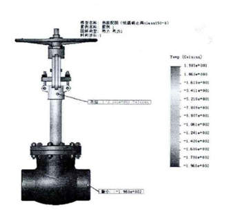
Figure 1 The temperature field of a globe valve without a draining board
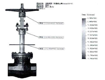
Figure 2 The temperature field of a globe valve with a draining board
The draining board can effectively slow down the transmission of the valve body's temperature to the packing and upper end of the valve stem, and further ensure that the temperature of the packing part and upper part of the valve stem is above 0°C. Figure 1 and Figure 2 are simulation diagrams of the temperature field of the entire valve body with and without the draining board respectively. By comparison, we can see that the temperature of the upper end of the valve bonnet with the draining board increases significantly. The temperature at the upper part of the extended valve bonnet is low. Normally, the valve is exposed to the air. The water vapor in the air will liquefy into water droplets when encountering the low-temperature valve bonnet. The diameter of the draining board exceeds that of the middle flange, which can prevent liquefied vapor caused by low temperatures from dripping on the flange's bolt, avoid the bolts from corroding and affecting online maintenance.
3. Design of pressure relief components
The volume of LNG after gasification is expanded by more than 600 times, and the problem of abnormal pressure rise is common to be seen. When the valve is closed, the LNG remaining in the valve body cavity absorbs a large amount of heat from the surrounding environment and quickly vaporizes, generating high pressure in the valve body, destroying the ball and valve seat components and making the valve unable to work normally. Therefore, a pressure relief hole is provided at the inlet end to ensure the smooth connection between the cavity and inlet pipe and prevent abnormal pressure rise of the cavity. The position indicated by the arrow in Figure 3 is the pressure relief hole of the LNG ultra-low temperature ball valve.
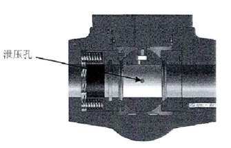
Figure 3 The pressure relief hole of ultra-low temperature ball valves
4. Anti-static structure design
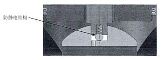
Figure 4 Anti-static structure of ball valves
LNG is flammable and explosive. Therefore, when designing LNG ultra-low temperature valves, it is necessary to design an anti-static structure. The material of the LNG ball valve seat is PCTFE. This material has a great potential for static electricity. Sparks caused by static electricity are likely to cause combustion of LNG or even explosion in the pipeline and valve body. Therefore, when designing a valve, it is necessary to design a conducting device to connect the valve stem and valve body so that the valve stem and closing part can discharge static electricity and eliminate safety hazards. Figure 4 shows the anti-static structure at the connection part between the ball and valve stem.
5. The structure design of the sealing
In order to ensure the safety and reliability of the valve's sealing at low temperatures, a special sealing structure should also be adopted when the sealing structure is designed. Leakages are easy to occur for sealing with only packing at low temperatures. We use three seals including lip seal rings, flexible graphite packing and O rings to ensure the sealing at the packing. The pre-tightening structure of disc spring sets is adopted to compensate deformation of the bolt when the temperature fluctuates. Meanwhile, the loosening of sealing members like packing is prevented after working for a long time. The sealing structure diagram is shown in Figure 5.
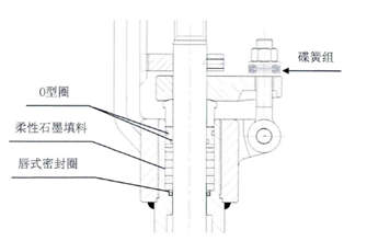
Figure 5 The structure of three seals
6. The structure design of fire protection
The connecting part of the valve body and bonnet adopts a double sealing structure of lip sealing rings and graphite spiral wound gaskets as shown in Figure 6. The sealing part of the valve stem seal also adopts a multiple sealing structure of lip sealing rings, graphite packing sets and O rings. When a fire occurs, the lip sealing ring melts and fails. At this time, the graphite wound gasket in the central cavity and the graphite packing set of the valve stem are mainly used for sealing to prevent leakages. The ball and valve seat adopt a dual sealing structure of metal valve seats and non-metallic sealing rings as shown in Figure 7. When a fire occurs, if the non-metallic sealing ring melts and fails, the metal valve seat of the second fire-proof sealing will push the valve seat to the sphere under the action of the spring's pretightening force to block the pipeline's fluid and prevent internal leakages.
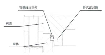
Figure 6 Double sealing structure of valve bodies and bonnets
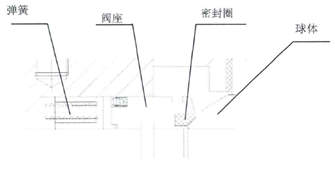
Figure 7 Double sealing structure of ball valve seats
7. Upward structural design of inverted sealing
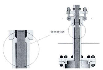
Figure 8 Upward design of inverted sealing
The Upward design of inverted sealing of the bonnet is shown in Figure 8, which ensures that the inverted seal is at a normal temperature position, is conducive to the sealing of the inverted seal structure and realizes replacement of packing and other seals.
8. The combination of stems
The valve stem is provided with a spring energy storage sealing ring, and the spring energy storage sealing ring closely adheres to the sealing groove as the medium pressure of the valve cavity increases, thereby forming a seal and ensuring the sealing effect of the valve stem. Anti blow structure of the valve stem is set. When the pressure in the valve cavity is abnormally increased, the valve stem will not be pushed. The disc spring set with pre-tighten packing is adopted to compensate for the loosening of sealing parts such as packing due to temperature fluctuations and long-term use. The structure is shown in Figure 9.
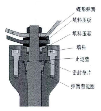
Figure 9 The combination of valve stems
9. Overall structure of ball valves
The three-dimensional assembly of the designed LNG ultra-low temperature ball valve is shown in Figure 10.
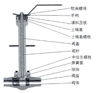
Figure 10 The overall structure of ball valves
2. The structure of the draining board
Figure 1 The temperature field of a globe valve without a draining board
Figure 2 The temperature field of a globe valve with a draining board
The draining board can effectively slow down the transmission of the valve body's temperature to the packing and upper end of the valve stem, and further ensure that the temperature of the packing part and upper part of the valve stem is above 0°C. Figure 1 and Figure 2 are simulation diagrams of the temperature field of the entire valve body with and without the draining board respectively. By comparison, we can see that the temperature of the upper end of the valve bonnet with the draining board increases significantly. The temperature at the upper part of the extended valve bonnet is low. Normally, the valve is exposed to the air. The water vapor in the air will liquefy into water droplets when encountering the low-temperature valve bonnet. The diameter of the draining board exceeds that of the middle flange, which can prevent liquefied vapor caused by low temperatures from dripping on the flange's bolt, avoid the bolts from corroding and affecting online maintenance.
3. Design of pressure relief components
The volume of LNG after gasification is expanded by more than 600 times, and the problem of abnormal pressure rise is common to be seen. When the valve is closed, the LNG remaining in the valve body cavity absorbs a large amount of heat from the surrounding environment and quickly vaporizes, generating high pressure in the valve body, destroying the ball and valve seat components and making the valve unable to work normally. Therefore, a pressure relief hole is provided at the inlet end to ensure the smooth connection between the cavity and inlet pipe and prevent abnormal pressure rise of the cavity. The position indicated by the arrow in Figure 3 is the pressure relief hole of the LNG ultra-low temperature ball valve.
Figure 3 The pressure relief hole of ultra-low temperature ball valves
4. Anti-static structure design
Figure 4 Anti-static structure of ball valves
LNG is flammable and explosive. Therefore, when designing LNG ultra-low temperature valves, it is necessary to design an anti-static structure. The material of the LNG ball valve seat is PCTFE. This material has a great potential for static electricity. Sparks caused by static electricity are likely to cause combustion of LNG or even explosion in the pipeline and valve body. Therefore, when designing a valve, it is necessary to design a conducting device to connect the valve stem and valve body so that the valve stem and closing part can discharge static electricity and eliminate safety hazards. Figure 4 shows the anti-static structure at the connection part between the ball and valve stem.
5. The structure design of the sealing
In order to ensure the safety and reliability of the valve's sealing at low temperatures, a special sealing structure should also be adopted when the sealing structure is designed. Leakages are easy to occur for sealing with only packing at low temperatures. We use three seals including lip seal rings, flexible graphite packing and O rings to ensure the sealing at the packing. The pre-tightening structure of disc spring sets is adopted to compensate deformation of the bolt when the temperature fluctuates. Meanwhile, the loosening of sealing members like packing is prevented after working for a long time. The sealing structure diagram is shown in Figure 5.
Figure 5 The structure of three seals
6. The structure design of fire protection
The connecting part of the valve body and bonnet adopts a double sealing structure of lip sealing rings and graphite spiral wound gaskets as shown in Figure 6. The sealing part of the valve stem seal also adopts a multiple sealing structure of lip sealing rings, graphite packing sets and O rings. When a fire occurs, the lip sealing ring melts and fails. At this time, the graphite wound gasket in the central cavity and the graphite packing set of the valve stem are mainly used for sealing to prevent leakages. The ball and valve seat adopt a dual sealing structure of metal valve seats and non-metallic sealing rings as shown in Figure 7. When a fire occurs, if the non-metallic sealing ring melts and fails, the metal valve seat of the second fire-proof sealing will push the valve seat to the sphere under the action of the spring's pretightening force to block the pipeline's fluid and prevent internal leakages.
Figure 6 Double sealing structure of valve bodies and bonnets
Figure 7 Double sealing structure of ball valve seats
7. Upward structural design of inverted sealing
Figure 8 Upward design of inverted sealing
The Upward design of inverted sealing of the bonnet is shown in Figure 8, which ensures that the inverted seal is at a normal temperature position, is conducive to the sealing of the inverted seal structure and realizes replacement of packing and other seals.
8. The combination of stems
The valve stem is provided with a spring energy storage sealing ring, and the spring energy storage sealing ring closely adheres to the sealing groove as the medium pressure of the valve cavity increases, thereby forming a seal and ensuring the sealing effect of the valve stem. Anti blow structure of the valve stem is set. When the pressure in the valve cavity is abnormally increased, the valve stem will not be pushed. The disc spring set with pre-tighten packing is adopted to compensate for the loosening of sealing parts such as packing due to temperature fluctuations and long-term use. The structure is shown in Figure 9.
Figure 9 The combination of valve stems
9. Overall structure of ball valves
The three-dimensional assembly of the designed LNG ultra-low temperature ball valve is shown in Figure 10.
Figure 10 The overall structure of ball valves

Baltic Valve
BALTIC VALVE CO., LTD supplies superior quality industrial valves covering ball valves, globe valves, gate valves, check valves, plug valves, butterfly valves, marine valves, forging steel valve, filter, etc.
Stay Connected
Latest News


DBB Ball Valves Available from Workshop Stock
Jun 30, 2026
Contact Us
Baltic Valve Co., Ltd.
Add: Baltic Valve Park, Siming, Xiamen, China.
Tel: +86 592 8266 140
Fax: +86 592 8266 440
Mail: [email protected]
Website: https://www.baltic-valve.com
Copyright © 2017-2026 Baltic Valve Co., Ltd. All rights reserved. Privacy Policy | Terms of Service
Website Design & Support: jeawin.com