The Analysis of the Sealing Force of Titanium Alloy Metal Seated Ball Valves
After calculating the sealing force of the titanium alloy metal seated ball valves with a size of 10 inches and pressure 300LB, the finite element analysis for sealing structure of seats is carried out to verify the rationality of the structure and the accuracy of the calculation, which is mainly for the sealing pressure ratio between the valve seat and the ball. The sphere and valve seat are made of ASME B381 F5 forgings, and the physical properties of the material are shown in Table 2.
Table 2 Physical properties of F5 forgings
Table 2 Physical properties of F5 forgings
| Performance | |
| Materials | Titanium alloys |
| Tensile strength | 895 |
| Yield strength | 828 |
| Elastic modulus E/MPa | 1.10 X10⁵ |
| Density | 4510 |
| Poisson's ratio | 0.32 |
1. Building an analysis model
The titanium alloy metal seated trunnion ball valve with a size of 10 inches and pressure of 300LB is simplified before analyzing the sealing specific pressure. To accurately reflect the real situation, try to reflect the details when the finite element modeling is set. However, it is often difficult to achieve in actual analysis. It is necessary to simplify the model. The principle of simplification is to keep the main part and ignore the details. For example, chamfers, roundings, and undercuts that have little influence can be ignored, the threaded surface is directly drawn as a cylindrical surface. Replace the threaded connection with a fixed connection. Remove the complicated and bulky drive system, valve body, valve stem and bracket. Only the sphere and valve seat are analyzed. Considering that the structure of the spherical valve seat is symmetrical structure, half of the model is established as the calculation model to save calculation time and reduce the amount of calculation. The simplified model is shown in figure 1.
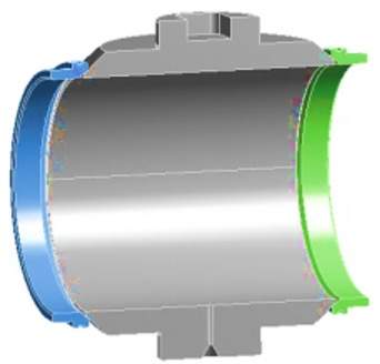
Figure 1 The analysis model of sealing specific pressure
2. Setting of boundary conditions
After completing the establishment of the analysis model, the model is meshed by the finite element analysis software Workbench. The mesh division adopts the adaptive type. The number of mesh elements after division is 110472 and the number of nodes is 198462. The mesh model is shown in Figure 2.
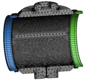
Figure 2 The mesh model
After the meshing is completed, the boundary conditions are set. To simplify the calculation, improve the efficiency of the analysis, and not affect the analysis effect, the connection constraints between the valve seat and spheres adopt the default binding constraints. Change the material properties to the properties of F5 forgings, and the detailed properties of material are shown in Table 2.
When carrying out the analysis of sealing specific pressure, the research is carried out under two working conditions: (1) the analysis of sealing specific pressure under the condition of preloading of the disc spring (2) the analysis of seal specific pressure under the rated working pressure: In order to display the stress distribution along the width direction of the sealing surface more intuitively and clearly, select the edge of the sealing surface and add a linear analysis path along the width direction.
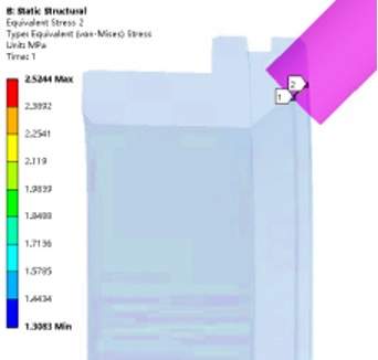
Figure 3 The distribution of the stress along the width direction under the action of preloading
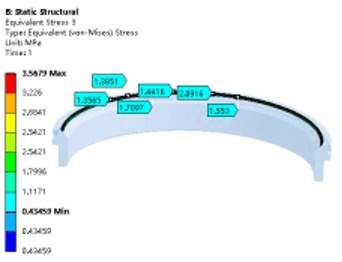
Figure 4 The distribution of stress on the sealing surface under the action of preloading
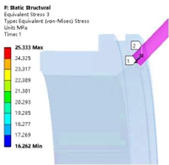
Figure 5 The distribution of stress along the width direction under rated pressure
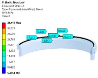
Figure 6 The stress of the sealing surface under rated pressure
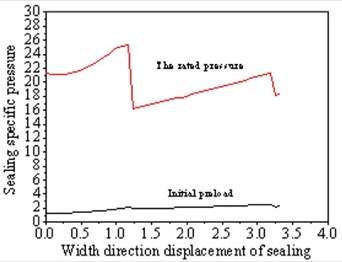
Figure 7 The changing curve of specific pressure along the width direction of the sealing surface
By analyzing the sealing specific pressure under the action of the initial preload of the disc spring and that under the rated working pressure, it can be seen from Figures 5 to 9 that the equivalent stress along the width direction of the sealing surface is mainly concentrated at between 1.3 and 2.5MPa. It is close to the theoretical calculation of the minimum preload specific pressure qmin. The linearly distributed equivalent stress along the width direction of the sealing surface under the rated working pressure is mainly concentrated between 16.26 and 25.33MPa, which is close to the theoretical calculation of the specific pressure of the sealing surface q. It can be seen from the analysis cloud diagram that the circumferential stress distribution along the sealing surface is uniform, and there is no insufficient stress or defects along the width direction, which meets the requirement for sealing for titanium alloy metal seated ball valves.
3. Conclusion
(1) The sealing specific pressure of the titanium alloy metal seated trunnion ball valve under the rated working pressure is mainly provided by the medium pressure. Therefore, to ensure the integrity of the hardened layer of the ball and valve seat of the titanium alloy metal seated ball valve, try as much as possible to avoid opening and closing valves under pressure in the debugging process.
(2) The results obtained by calculation and analysis are close, and the deviation is about 14% to 25%. The main reason is related to the quality of the mesh and model, but it has a good guiding significance for the research on the sealing specific pressure of titanium alloy metal seated ball valves. The analysis results can provide a basis for the design of the sealing specific pressure. Through the finite element analysis of the sealing specific pressure of the metal seated ball valve with 10 inches and pressure of 300LB, the stress of the sealing surface can be more intuitively reflected, and provide a reference for structural optimization design and performance improvement.
(3) Reducing the preloading force of the disc spring and initial preloading specific pressure can effectively avoid damage to the surface caused by the repeated opening and closing of the titanium alloy metal seated ball valve. This method should ensure that the disc spring can provide the initial preload force of not less than 1MPa, and the calculated sealing specific pressure under the rated pressure should not be less than specific pressure.

Baltic Valve
BALTIC VALVE CO., LTD supplies superior quality industrial valves covering ball valves, globe valves, gate valves, check valves, plug valves, butterfly valves, marine valves, forging steel valve, filter, etc.
Stay Connected
Latest News


DBB Ball Valves Available from Workshop Stock
Jun 30, 2026
Contact Us
Baltic Valve Co., Ltd.
Add: Baltic Valve Park, Siming, Xiamen, China.
Tel: +86 592 8266 140
Fax: +86 592 8266 440
Mail: [email protected]
Website: https://www.baltic-valve.com
Copyright © 2017-2026 Baltic Valve Co., Ltd. All rights reserved. Privacy Policy | Terms of Service
Website Design & Support: jeawin.com