Structural Design & Optimization of Limit Locking of Ball Valves
1. Overview
A ball valve is a kind of rotary valve with a ball as the opening and closing part. The main driving modes of ball valves are manual, electric, pneumatic, electro-hydraulic, and gas-hydraulic modes. In order to avoid human error and ensure the safe operation of the device system, it is necessary to limit the position of the ball valve to keep it in the correct position.
2. Limit locking structure with drive devices for ball valves
Manual valves mainly refer to handwheel operation and wrench operation. To ensure that the valve can be opened and closed, the maximum thrust acting on the handwheel and wrench should not exceed 360N. For the ball valve, the handwheel operation mainly refers to the handwheel on the worm gearbox. The limit of the worm gearbox ball valve and the electric, pneumatic, electro-hydraulic linkage, and gas-hydraulic linkage are generally realized through the internal structure of its driving device.
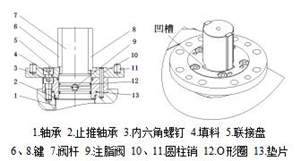
Figure 1 The self-limiting structure of the ball valve with drive devices
The self-limiting structure of the ball valve with drive devices is shown in Figure 1. The common limiting structure is to set a groove at the valve's connecting plate, and the self-limiting of the valve is realized by the key on the valve stem and the groove of the connecting plate abutting each other. The locking function of the ball valve with drive devices can be realized by matching with the drive device through lead seals, wire locks, padlocks, chain locks, single locks and interlocks.
3. Manual ball valve limit locking structure operated by wrenches
The common ball valve with self-limiting locking functions operated by wrenches includes the limit locking of the pressure plate bolt and pressure plate shoulder, and the locking of the limit handle of the limit tube.
3.1 Limit locking of pressure plate bolts
The limit locking structure of the pressure plate bolt is shown in Figure 2. The end face of the 2 sides of the tail of the positioning plate is in contact with the inner hexagon socket head cap screw disk, realizing the limit locking of the valve. Two lug locking holes are arranged on the upper part of the pressing plate and mutually form an angle of 90° with the central axis. The positions of the locking holes correspond to the locking holes of the positioning plate. When the valve is in the fully open position, the locking hole of the positioning plate corresponds to the locking hole I of the pressure plate; when the valve is in the fully closed position, the locking hole of the positioning plate corresponds to the locking hole II of the pressure plate.
The packing pressing plate and hexagon socket head cap screws of the pressing plate bolt limit locking structure are pressure bearing parts, which directly bear the sealing force of the packing. At the same time, the hexagon socket head screw disc will be impacted by the end of the positioning plate. When the valve is repeatedly opened and closed for a long time, the screw of the pressing plate will be loosened, and there is a risk of fatigue shear stress, leading to the failure of the pressure boundary.
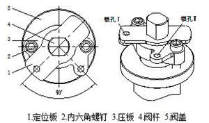
Figure 2 The self-limiting structure of the ball valve with drive devices
3.2 Limit locking of platen shoulders
The limit locking structure of the pressure plate shoulder is shown in Figure 3. The end face of the 2 sides of the tail of the positioning plate is in contact with the end face of the pressure plate shoulder to realize the limit locking of the valve. Two shoulders corresponding to the positioning plate are arranged on the packing pressing plate, and locking holes corresponding to the positioning plate are arranged on the packing pressing plate at the same time. The shoulder of the pressure plate slows down the lateral impact load from the positioning plate to the pressure plate bolt, but the setting of the lock hole on the pressure plate weakens the strength of the pressure plate. The structure has the potential risk of the failure of the pressure plate.
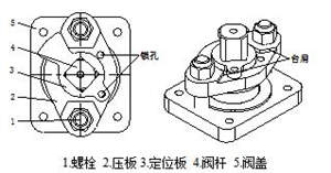
Figure 3 The self-limiting structure of the ball valve with drive devices
3.3 Limit handle locking of the limit tube
The locking structure of the limit handle of the limit tube is shown in Figure 4. The end face of the two sides of the handle is in contact with the limit tube on the valve bonnet to realize the switch limit of the valve. The lock hole of the handle head and half-crescent positioning plate realize the locking function. One end of the limiting tube is inserted into the countersunk hole of the valve bonnet, and the other end is abutted with the positioning plate through the inner hexagon screw. The handle is arranged between the positioning plate and the pressing plate.
This structure has more advantages than the limit locking of the pressure plate bolt and the limit locking of the pressure plate shoulder. In the process of fully opening and closing the valve, the lateral impact load generated by the handle first acts on the limit tube, and then is transmitted to the hexagon socket head screw so as to avoid the impact of the lateral load on the pressure plate bearing screw. The structure is relatively complex due to the limitation of the spatial position. The handle is generally made of sheet metal. The limit hexagon socket head cap screw is repeatedly subjected to lateral impact loads from the handle, and there is also a risk of shear failure.
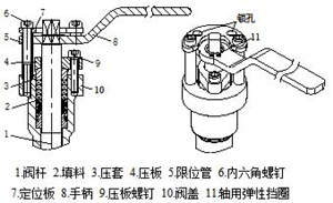
Figure 4 The self-limiting structure of the ball valve with drive devices
4. New manual limit locking structure of ball valves
On the basis of the existing three kinds of manual ball valves with self-limiting locking functions, the structural optimization design is carried out. The rotation angle of the handle is limited by the circular positioning plate and bracket shoulder, so that it can only be rotated within a range of 90° and the ball valve can be accurately opened or completely closed. The main structure of the new manual ball valve's limit lock is shown in Figure 5.
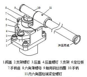
Figure 5 The self-limiting structure of the ball valve with drive devices
4.1 Handle bases
The handle base is provided with a through hole that can get through the handle, and the handle can be made of seamless steel pipes. One end of the seamless steel pipe is punched to form a bell mouth, and the other end is machined with a groove for installing a steel wire retaining ring for the shaft. Compared with the limit handle locking structure of the limit pipe in the prior art, when the operating torque of the valve increases, the seamless steel pipe can move flexibly in the handle seat hole, and the length can be freely extended, making opening and closing of the valve more labor-saving. When the valve is installed on the pipeline and is in the open or closed position for a long time, the seamless steel pipe can be removed from the pipeline at any time, ensuring the safety and reliability of the pipeline system.
4.2 Circular positioning plates
The circular positioning plate is provided with a lug that forms an angle of 90° with the center (Figure 6), and two lock holes are set at the center of the lug; a notch abutting against the shoulder of the bracket is processed on the symmetrical surface of the lug. The center of the positioning plate is provided with a through hole that is parallel to the flat shaft of the valve stem. The flat shaft of the valve stem penetrates through the through hole and abuts against the vertical flat hole of the handle seat. When the handle drives the valve stem to rotate, the positioning plate also follows the rotation.
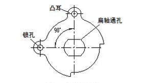
Figure 6 The structure of the positioning plate
4.3 Brackets
There is a lug on the upper part of the bracket (Figure 7), a lock hole in the center of the lug, a shoulder on the opposite side of the lug, 4 stand bars at the bottom of the bracket, and a through-hole fixed with the threaded hole of the valve bonnet on the stand bars. Use the bracket screws to fasten the bracket to the valve bonnet. During assembly, the positioning plate is fixed above the bracket, and the inner side of the positioning plate gap abuts the two sides of the shoulder above the bracket, so that the positioning plate can only rotate within an angle of 90°, thus eliminating the safety hazard caused by the valve not being completely closed.
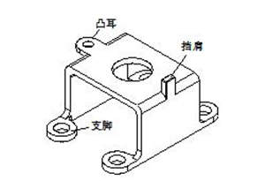
Figure 7 The structure of the bracket
5. Conclusion
The new manual limit locking structure of the ball valve designed in this article realizes the limit locking of the ball valve through the circular positioning plate and the bracket shoulder. The advantages of this structure are as follows:
(1) The handle seat and seamless steel pipe are used to make the opening and closing of the valve more flexible and labor-saving. When the valve is installed on the pipeline and is in the open or closed position for a long time, the seamless steel pipe can be removed from the pipeline at any time to ensure the safety and reliability of the pipeline system.
A ball valve is a kind of rotary valve with a ball as the opening and closing part. The main driving modes of ball valves are manual, electric, pneumatic, electro-hydraulic, and gas-hydraulic modes. In order to avoid human error and ensure the safe operation of the device system, it is necessary to limit the position of the ball valve to keep it in the correct position.
2. Limit locking structure with drive devices for ball valves
Manual valves mainly refer to handwheel operation and wrench operation. To ensure that the valve can be opened and closed, the maximum thrust acting on the handwheel and wrench should not exceed 360N. For the ball valve, the handwheel operation mainly refers to the handwheel on the worm gearbox. The limit of the worm gearbox ball valve and the electric, pneumatic, electro-hydraulic linkage, and gas-hydraulic linkage are generally realized through the internal structure of its driving device.
Figure 1 The self-limiting structure of the ball valve with drive devices
The self-limiting structure of the ball valve with drive devices is shown in Figure 1. The common limiting structure is to set a groove at the valve's connecting plate, and the self-limiting of the valve is realized by the key on the valve stem and the groove of the connecting plate abutting each other. The locking function of the ball valve with drive devices can be realized by matching with the drive device through lead seals, wire locks, padlocks, chain locks, single locks and interlocks.
3. Manual ball valve limit locking structure operated by wrenches
The common ball valve with self-limiting locking functions operated by wrenches includes the limit locking of the pressure plate bolt and pressure plate shoulder, and the locking of the limit handle of the limit tube.
3.1 Limit locking of pressure plate bolts
The limit locking structure of the pressure plate bolt is shown in Figure 2. The end face of the 2 sides of the tail of the positioning plate is in contact with the inner hexagon socket head cap screw disk, realizing the limit locking of the valve. Two lug locking holes are arranged on the upper part of the pressing plate and mutually form an angle of 90° with the central axis. The positions of the locking holes correspond to the locking holes of the positioning plate. When the valve is in the fully open position, the locking hole of the positioning plate corresponds to the locking hole I of the pressure plate; when the valve is in the fully closed position, the locking hole of the positioning plate corresponds to the locking hole II of the pressure plate.
The packing pressing plate and hexagon socket head cap screws of the pressing plate bolt limit locking structure are pressure bearing parts, which directly bear the sealing force of the packing. At the same time, the hexagon socket head screw disc will be impacted by the end of the positioning plate. When the valve is repeatedly opened and closed for a long time, the screw of the pressing plate will be loosened, and there is a risk of fatigue shear stress, leading to the failure of the pressure boundary.
Figure 2 The self-limiting structure of the ball valve with drive devices
3.2 Limit locking of platen shoulders
The limit locking structure of the pressure plate shoulder is shown in Figure 3. The end face of the 2 sides of the tail of the positioning plate is in contact with the end face of the pressure plate shoulder to realize the limit locking of the valve. Two shoulders corresponding to the positioning plate are arranged on the packing pressing plate, and locking holes corresponding to the positioning plate are arranged on the packing pressing plate at the same time. The shoulder of the pressure plate slows down the lateral impact load from the positioning plate to the pressure plate bolt, but the setting of the lock hole on the pressure plate weakens the strength of the pressure plate. The structure has the potential risk of the failure of the pressure plate.
Figure 3 The self-limiting structure of the ball valve with drive devices
3.3 Limit handle locking of the limit tube
The locking structure of the limit handle of the limit tube is shown in Figure 4. The end face of the two sides of the handle is in contact with the limit tube on the valve bonnet to realize the switch limit of the valve. The lock hole of the handle head and half-crescent positioning plate realize the locking function. One end of the limiting tube is inserted into the countersunk hole of the valve bonnet, and the other end is abutted with the positioning plate through the inner hexagon screw. The handle is arranged between the positioning plate and the pressing plate.
This structure has more advantages than the limit locking of the pressure plate bolt and the limit locking of the pressure plate shoulder. In the process of fully opening and closing the valve, the lateral impact load generated by the handle first acts on the limit tube, and then is transmitted to the hexagon socket head screw so as to avoid the impact of the lateral load on the pressure plate bearing screw. The structure is relatively complex due to the limitation of the spatial position. The handle is generally made of sheet metal. The limit hexagon socket head cap screw is repeatedly subjected to lateral impact loads from the handle, and there is also a risk of shear failure.
Figure 4 The self-limiting structure of the ball valve with drive devices
4. New manual limit locking structure of ball valves
On the basis of the existing three kinds of manual ball valves with self-limiting locking functions, the structural optimization design is carried out. The rotation angle of the handle is limited by the circular positioning plate and bracket shoulder, so that it can only be rotated within a range of 90° and the ball valve can be accurately opened or completely closed. The main structure of the new manual ball valve's limit lock is shown in Figure 5.
Figure 5 The self-limiting structure of the ball valve with drive devices
4.1 Handle bases
The handle base is provided with a through hole that can get through the handle, and the handle can be made of seamless steel pipes. One end of the seamless steel pipe is punched to form a bell mouth, and the other end is machined with a groove for installing a steel wire retaining ring for the shaft. Compared with the limit handle locking structure of the limit pipe in the prior art, when the operating torque of the valve increases, the seamless steel pipe can move flexibly in the handle seat hole, and the length can be freely extended, making opening and closing of the valve more labor-saving. When the valve is installed on the pipeline and is in the open or closed position for a long time, the seamless steel pipe can be removed from the pipeline at any time, ensuring the safety and reliability of the pipeline system.
4.2 Circular positioning plates
The circular positioning plate is provided with a lug that forms an angle of 90° with the center (Figure 6), and two lock holes are set at the center of the lug; a notch abutting against the shoulder of the bracket is processed on the symmetrical surface of the lug. The center of the positioning plate is provided with a through hole that is parallel to the flat shaft of the valve stem. The flat shaft of the valve stem penetrates through the through hole and abuts against the vertical flat hole of the handle seat. When the handle drives the valve stem to rotate, the positioning plate also follows the rotation.
Figure 6 The structure of the positioning plate
4.3 Brackets
There is a lug on the upper part of the bracket (Figure 7), a lock hole in the center of the lug, a shoulder on the opposite side of the lug, 4 stand bars at the bottom of the bracket, and a through-hole fixed with the threaded hole of the valve bonnet on the stand bars. Use the bracket screws to fasten the bracket to the valve bonnet. During assembly, the positioning plate is fixed above the bracket, and the inner side of the positioning plate gap abuts the two sides of the shoulder above the bracket, so that the positioning plate can only rotate within an angle of 90°, thus eliminating the safety hazard caused by the valve not being completely closed.
Figure 7 The structure of the bracket
5. Conclusion
The new manual limit locking structure of the ball valve designed in this article realizes the limit locking of the ball valve through the circular positioning plate and the bracket shoulder. The advantages of this structure are as follows:
(1) The handle seat and seamless steel pipe are used to make the opening and closing of the valve more flexible and labor-saving. When the valve is installed on the pipeline and is in the open or closed position for a long time, the seamless steel pipe can be removed from the pipeline at any time to ensure the safety and reliability of the pipeline system.
(2)The bracket shoulder and the circular positioning plate limit the opening and closing of the valve within the range of 90°, which accurately realizes the limit locking function of the manual valve and avoids the lateral impact load generated by the positioning plate on the pressure plate bolt in the opening and closing process. When the handle is rotated, the lateral load generated is transmitted to the 4 stand bar screws of the bracket through the bracket shoulder to avoid the lateral shear force of the pressure plate bolts.
(3) The design is reasonable and the stability is good, which improves the accuracy of the rotation of the handle, avoids the problem of weakening the strength of the pressure plate caused by setting a lock hole on the pressure plate, ensures the reliability of the packing seal, and prolongs the service life of the valve.

Baltic Valve
BALTIC VALVE CO., LTD supplies superior quality industrial valves covering ball valves, globe valves, gate valves, check valves, plug valves, butterfly valves, marine valves, forging steel valve, filter, etc.
Stay Connected
Latest News


DBB Ball Valves Available from Workshop Stock
Jun 30, 2026
Contact Us
Baltic Valve Co., Ltd.
Add: Baltic Valve Park, Siming, Xiamen, China.
Tel: +86 592 8266 140
Fax: +86 592 8266 440
Mail: [email protected]
Website: https://www.baltic-valve.com
Copyright © 2017-2026 Baltic Valve Co., Ltd. All rights reserved. Privacy Policy | Terms of Service
Website Design & Support: jeawin.com