The Fault Diagnosis Technology for Valves at Home and Abroad (Part Two)
Failure mechanisms and symptoms of valves
Understanding the mechanism and manifestation of valve faults is the basis for valve fault diagnosis. Yan Huang and others discussed the features, causes, and main patterns of the failure of the valve. Ying Zhang used theories of aeroacoustics, gas jet and vortex motion to analyze the internal leakage process of the valve's gas medium. He believed that the quadrupole sound source can be used to approximate the noise source of the valve's internal leakage and jet flow, and established the relationship among internal leakage jet velocity and jet intensity and noise intensity. Qianxia Gao and others believed that when the valve has internal leakage, a fluctuating pressure field will be generated at the leak, forming a multi-phase turbulent jet. The multi-phase turbulent jet will generate a variety of acoustic emission source signals, which can be used as a signal to monitor leakages of valves. South Korea started monitoring the status of electric valves in nuclear power plants in 1998. Kim and others believed that the stem factor was the main parameter to measure the output thrust of the stem of the electric gate valve, and the stem factor SF was the ratio of the output torque of the electric head to the stem thrust, that is
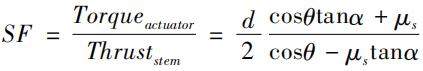
In the formula, d is the diameter of the stem thread. θ is the thread angle. Ɑ is the half of θ. μs is the friction coefficient of the stem.
In the daily use of the valve, the selection of valve materials, the lubrication of the valve stem and the dynamic pressure difference generated by the medium will all affect the output of the valve stem's thrust. After normalization, the larger the stem factor is, the smaller the output thrust of the stem becomes. However, when the valve stem factor is greater than 0.2, the output force of the valve stem is no longer significantly smaller. When Bing Dai and others diagnosed a valve from Qinshan Associated Company, they found that the motor's opening stroke power fluctuated, and the curve was sawtooth. The cycle of the wave crest was 2.3s, and the time for the valve stem to rotate one circle was also 2.3s. It was inferred that the gland of the valve stem was improperly assembled. After the valve was disassembled, it was found that there was indeed a misalignment between the valve stem and the worm gear.
Intelligent decision
The intelligent decision-making of valve fault diagnosis is to effectively obtain, transmit and process diagnostic information, and simulate human experts to judge and make decisions on the operating status and faults of the valve. This plays a very important role in optimizing the valve maintenance program and reducing valve maintenance costs. Taking a million-kilowatt nuclear power plant as an example, the valve's investment accounts for 3.8% of the equipment supply cost, but the annual maintenance cost of the valve accounts for half of the total power plant maintenance expenditure. In the classification of valve fault types, artificial neural network is the most commonly used method. Karpenko and others designed a multi-layer forward artificial neural network for pneumatic control valve faults; valve dynamic errors, dead zones, hysteresis, and other parameters such as dead center setting are input, which distinguishes faults such as blocking of exhaust ports, and leakages of diaphragms. Lee and others used artificial neural networks to diagnose check valves in nuclear power plants. Through training, the method can identify whether the internal leakage is caused by the wear of valve discs or falling foreign objects. This method can further infer the wear amount of the valve disc and the size of the foreign body. Huafeng Qi studied the diagnostic effects of BP, RBF and Elman neural networks on electro-hydraulic servo valves in nuclear power plants. The results showed that RBF neural network was superior to the other two methods in terms of real-time diagnosis and accuracy of fault classifications. Goncalves and others used Kohonen mapping to predict different faults such as torque, displacement or closing time of electric valves. Bo and others proposed a non-parameter statistical hypothesis test to diagnose the gap, dead zone, leakage and blockage of the regulating valve. By the central moment of the sensor signal, the fault was classified using the likelihood ratio test. Gang Qiao used the failure mode analysis to analyze the main failure and failure modes of the electric heavy water isolation valve, and established a fault tree. The research results optimized the frequency of valve testing and reduced the cost of valve maintenance. The research results optimized the frequency of valve testing and reduced the cost of valve maintenance. Guofeng Yang and others used a simplified mathematical model and a pattern recognition technology to perform fuzzy inference on the operating data of safety-level electric isolation valves in nuclear power plants, and calculated the closeness of the data to the standard failure mode, thereby identifying the type of valve failure. Xinya Chen from North China Electric Power University designed a bus-type electric actuator for online diagnosis of electric valves. A valve fault diagnosis expert system was compiled by using VC++ and CLIPS tools based on this. A relatively complete diagnosis rule knowledge base was established and 10 kinds of fault symptom type discriminant function algorithms were summarized.
Industrial products
At present, some products that can be used to carry out valve fault diagnosis in the industrial field have appeared, and they are mainly divided into three categories: bus types, mobile types and handheld types. The bus type diagnosis system is generally used for diagnosing the regulating valve equipped with the intelligent electric head, and carries out data communication through the HART bus. Mobile diagnostic equipment mainly includes QuikLook from Tele-dyne, Viper and VOTES INFINITY from Crane Nuclear, and SIPLUG DAW3 from Areva. Among them, Crane's Viper is mainly used for the diagnosis and calibration of pneumatic valves. SIPLUG is mainly used for the diagnosis and calibration of electric valves, and QuikLook and VOTES INFINITY have both diagnosis functions for electric and pneumatic valves. Crane's diagnostic products have been applied to six nuclear power units in China, and the main users of Teledyne's products include Velan in Canada, Weir in the United Kingdom, FlowServe in the United States, and Taiwan Power Corporation. Avera has launched SIPLUGSOVMobile, that is, the world's only mobile solenoid valve diagnostic device, which judges the healthy state of solenoid valves by measuring the current, voltage, coil resistance and temperature of the solenoid valve. The equipment has been used in the Beznau nuclear power plant in Switzerland, the Gundremmingen, Grohnde, Grafenrheinfeld and Neckarwestheim nuclear power plants in Germany, and the Trillo nuclear power plant in Spain. In the future, its bus-based version will be used in the Olkiuoto nuclear power plant in Finland. Hand-held diagnostic devices are mainly Fisher's products based on ValveLink Mobile software, including customized handheld devices, PDAs, and even smart phones with Windows systems. The handheld device communicates with the valve positioner via Bluetooth, performs related tests, and obtains the operating parameters of the valve.
In terms of detection equipment of the valve's internal leakage, there are mainly VPAC II from Mis-tras Group in the United States and MIDAS Meter from Score Group in the United Kingdom, both of which are quantitative detection equipment for leakages of valves based on the principle of acoustic emission. When the valve in the closed state is subjected to a certain pressure, the minimum leakage that this type of equipment can detect is about 1L/min. Affected by ambient noise, detection locations and pressure, the error of leakage detection is between 50% and 200%.
The valve manufacturer uses the valve diagnostic equipment to perform multiple tests (Baseline Tests) on the valves to obtain average values and fluctuation ranges of the key parameters. After the valve is delivered to the site for use, the user will use similar equipment to test the key parameters of the valve online in a certain period. If the test result is within the range of the manufacturer's test result, the valve is considered qualified and does not need to be maintained. Otherwise, the valve needs to be repaired and adjusted until the final test result is within the factory's range again.
Understanding the mechanism and manifestation of valve faults is the basis for valve fault diagnosis. Yan Huang and others discussed the features, causes, and main patterns of the failure of the valve. Ying Zhang used theories of aeroacoustics, gas jet and vortex motion to analyze the internal leakage process of the valve's gas medium. He believed that the quadrupole sound source can be used to approximate the noise source of the valve's internal leakage and jet flow, and established the relationship among internal leakage jet velocity and jet intensity and noise intensity. Qianxia Gao and others believed that when the valve has internal leakage, a fluctuating pressure field will be generated at the leak, forming a multi-phase turbulent jet. The multi-phase turbulent jet will generate a variety of acoustic emission source signals, which can be used as a signal to monitor leakages of valves. South Korea started monitoring the status of electric valves in nuclear power plants in 1998. Kim and others believed that the stem factor was the main parameter to measure the output thrust of the stem of the electric gate valve, and the stem factor SF was the ratio of the output torque of the electric head to the stem thrust, that is
In the formula, d is the diameter of the stem thread. θ is the thread angle. Ɑ is the half of θ. μs is the friction coefficient of the stem.
In the daily use of the valve, the selection of valve materials, the lubrication of the valve stem and the dynamic pressure difference generated by the medium will all affect the output of the valve stem's thrust. After normalization, the larger the stem factor is, the smaller the output thrust of the stem becomes. However, when the valve stem factor is greater than 0.2, the output force of the valve stem is no longer significantly smaller. When Bing Dai and others diagnosed a valve from Qinshan Associated Company, they found that the motor's opening stroke power fluctuated, and the curve was sawtooth. The cycle of the wave crest was 2.3s, and the time for the valve stem to rotate one circle was also 2.3s. It was inferred that the gland of the valve stem was improperly assembled. After the valve was disassembled, it was found that there was indeed a misalignment between the valve stem and the worm gear.
Intelligent decision
The intelligent decision-making of valve fault diagnosis is to effectively obtain, transmit and process diagnostic information, and simulate human experts to judge and make decisions on the operating status and faults of the valve. This plays a very important role in optimizing the valve maintenance program and reducing valve maintenance costs. Taking a million-kilowatt nuclear power plant as an example, the valve's investment accounts for 3.8% of the equipment supply cost, but the annual maintenance cost of the valve accounts for half of the total power plant maintenance expenditure. In the classification of valve fault types, artificial neural network is the most commonly used method. Karpenko and others designed a multi-layer forward artificial neural network for pneumatic control valve faults; valve dynamic errors, dead zones, hysteresis, and other parameters such as dead center setting are input, which distinguishes faults such as blocking of exhaust ports, and leakages of diaphragms. Lee and others used artificial neural networks to diagnose check valves in nuclear power plants. Through training, the method can identify whether the internal leakage is caused by the wear of valve discs or falling foreign objects. This method can further infer the wear amount of the valve disc and the size of the foreign body. Huafeng Qi studied the diagnostic effects of BP, RBF and Elman neural networks on electro-hydraulic servo valves in nuclear power plants. The results showed that RBF neural network was superior to the other two methods in terms of real-time diagnosis and accuracy of fault classifications. Goncalves and others used Kohonen mapping to predict different faults such as torque, displacement or closing time of electric valves. Bo and others proposed a non-parameter statistical hypothesis test to diagnose the gap, dead zone, leakage and blockage of the regulating valve. By the central moment of the sensor signal, the fault was classified using the likelihood ratio test. Gang Qiao used the failure mode analysis to analyze the main failure and failure modes of the electric heavy water isolation valve, and established a fault tree. The research results optimized the frequency of valve testing and reduced the cost of valve maintenance. The research results optimized the frequency of valve testing and reduced the cost of valve maintenance. Guofeng Yang and others used a simplified mathematical model and a pattern recognition technology to perform fuzzy inference on the operating data of safety-level electric isolation valves in nuclear power plants, and calculated the closeness of the data to the standard failure mode, thereby identifying the type of valve failure. Xinya Chen from North China Electric Power University designed a bus-type electric actuator for online diagnosis of electric valves. A valve fault diagnosis expert system was compiled by using VC++ and CLIPS tools based on this. A relatively complete diagnosis rule knowledge base was established and 10 kinds of fault symptom type discriminant function algorithms were summarized.
Industrial products
At present, some products that can be used to carry out valve fault diagnosis in the industrial field have appeared, and they are mainly divided into three categories: bus types, mobile types and handheld types. The bus type diagnosis system is generally used for diagnosing the regulating valve equipped with the intelligent electric head, and carries out data communication through the HART bus. Mobile diagnostic equipment mainly includes QuikLook from Tele-dyne, Viper and VOTES INFINITY from Crane Nuclear, and SIPLUG DAW3 from Areva. Among them, Crane's Viper is mainly used for the diagnosis and calibration of pneumatic valves. SIPLUG is mainly used for the diagnosis and calibration of electric valves, and QuikLook and VOTES INFINITY have both diagnosis functions for electric and pneumatic valves. Crane's diagnostic products have been applied to six nuclear power units in China, and the main users of Teledyne's products include Velan in Canada, Weir in the United Kingdom, FlowServe in the United States, and Taiwan Power Corporation. Avera has launched SIPLUGSOVMobile, that is, the world's only mobile solenoid valve diagnostic device, which judges the healthy state of solenoid valves by measuring the current, voltage, coil resistance and temperature of the solenoid valve. The equipment has been used in the Beznau nuclear power plant in Switzerland, the Gundremmingen, Grohnde, Grafenrheinfeld and Neckarwestheim nuclear power plants in Germany, and the Trillo nuclear power plant in Spain. In the future, its bus-based version will be used in the Olkiuoto nuclear power plant in Finland. Hand-held diagnostic devices are mainly Fisher's products based on ValveLink Mobile software, including customized handheld devices, PDAs, and even smart phones with Windows systems. The handheld device communicates with the valve positioner via Bluetooth, performs related tests, and obtains the operating parameters of the valve.
In terms of detection equipment of the valve's internal leakage, there are mainly VPAC II from Mis-tras Group in the United States and MIDAS Meter from Score Group in the United Kingdom, both of which are quantitative detection equipment for leakages of valves based on the principle of acoustic emission. When the valve in the closed state is subjected to a certain pressure, the minimum leakage that this type of equipment can detect is about 1L/min. Affected by ambient noise, detection locations and pressure, the error of leakage detection is between 50% and 200%.
The valve manufacturer uses the valve diagnostic equipment to perform multiple tests (Baseline Tests) on the valves to obtain average values and fluctuation ranges of the key parameters. After the valve is delivered to the site for use, the user will use similar equipment to test the key parameters of the valve online in a certain period. If the test result is within the range of the manufacturer's test result, the valve is considered qualified and does not need to be maintained. Otherwise, the valve needs to be repaired and adjusted until the final test result is within the factory's range again.

Baltic Valve
BALTIC VALVE CO., LTD supplies superior quality industrial valves covering ball valves, globe valves, gate valves, check valves, plug valves, butterfly valves, marine valves, forging steel valve, filter, etc.
Stay Connected
Latest News


DBB Ball Valves Available from Workshop Stock
Jun 30, 2026
Contact Us
Baltic Valve Co., Ltd.
Add: Baltic Valve Park, Siming, Xiamen, China.
Tel: +86 592 8266 140
Fax: +86 592 8266 440
Mail: [email protected]
Website: https://www.baltic-valve.com
Copyright © 2017-2026 Baltic Valve Co., Ltd. All rights reserved. Privacy Policy | Terms of Service
Website Design & Support: jeawin.com