Kinetic Analysis and Reliability of Pneumatic Cryogenic Gate Valves with Open Spheres
The kinetic analysis and reliability demonstration of the main parts of the gate valve under low-temperature conditions have provided a theoretical basis for the development and application of the gate valve.
1. Kinetic analysis
In the cooling process of the system, the valve structure will produce uncoordinated stress and deformation, which may cause excessive stress and deformation and affect the sealing, opening and closing of the valve. The low-temperature gate valve with opened sphere has a fast opening and closing time of 2 to 3 seconds in a low-temperature medium, and the inertial force of the moving parts will generate additional loads. Through dynamic analysis and research, the transient temperature field and transient stress of the valve are obtained to ensure the sealing reliability of the temperature load, pressure load and additional load and the structural integrity of the pressure boundary of the valve under low-temperature conditions.
The analysis of the transient temperature field
Open the valve. Heat convection occurs for the inner wall of the valve body and bonnet and liquid nitrogen (-196°C), and the outer wall of the valve is insulated. Heat transfer free convection happens between the outer wall of the bonnet and the environment. The heat transfer process in the valve is the coupled contact heat transfer of liquid and solid phases. The fluid calculation software is used to couple the transient temperature field distribution of the valve. The convective heat transfer coefficient of the valve is shown in Table 1.
Table 1 Convective heat transfer coefficients
| Parts | Working conditions | Working media | Temperatures/℃ | Convection coefficients of valve bodies, bonnets and working media w/(mK) |
| Valve bonnets | Opening | Liquid nitrogen | -196℃ | 2.884x10⁴ (inner walls) |
| Air | 29℃ | 10 (outer walls) | ||
| Valve bodies | Opening | Liquid nitrogen | -196℃ | 2.884x10⁴ (inner walls) |
| Air | 29℃ | 0 (outer walls) |
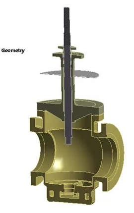
Figure 1 The three-dimensional model of valves
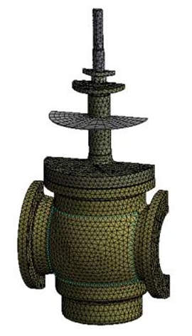
Figure 2 The grid division of valves
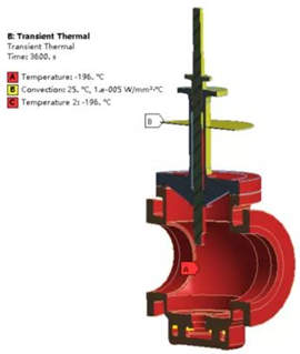
Figure 3 The temperature boundary conditions of valves
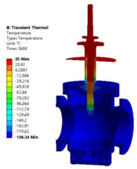
Figure 4 The transient surface temperature field of valves
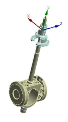
Figure 5 The simplified model
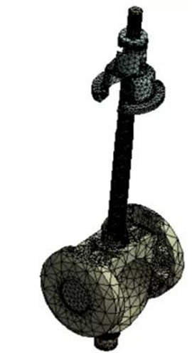
Figure 6 The grid diagram of the simplified model
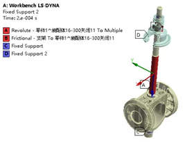
Figure 7 Fixed constraint and rotation constraint
2. The analysis of reliability
The BP neural network optimized by the genetic algorithm is used to establish the maximum stress prediction of the spherical gate valve, and the obtained prediction model is used to calculate the strength-stress interference model; the reliability and fuzzy reliability calculation program are compiled by using Matlab. The Monte Carlo method is used to sample 10,000 times and obtain calculation results of reliability.
The reliability analysis of the valve body
A fixed constraint A is applied to the inlet end of the valve body, and a displacement constraint C is applied to the outlet end. Design pressure of 5MPa is applied to the inlet and outlet ends of the valve body and the inner wall of the middle cavity, and a bolt compression force of 131.889kN and a gasket sealing force of 124.820kN are applied to the middle flange stop. Constraints and loading are shown in Figure 13.
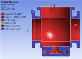
Figure 8 Restraints and applied loads of valves
Stress analysis results
It can be seen from the distribution of the valve's stress field (Figure 14) that when manufacturing errors are not considered, the maximum stress of the valve body is 160.4MPa, which is less than the allowable stress specified in the standard.
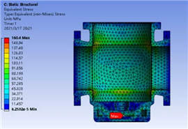
Figure 9 The stress distribution of the valve
The analysis results of reliability
Figure 15 shows the equivalent stress by sampling 10,000 samples. According to the mathematical model obtained, the strength reliability of the spherical gate valve body is close to 99.99%.
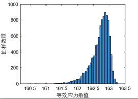
Figure 10 The diagram of the equivalent stress distribution
The reliability analysis of valve plates
Restraint and loads of valve plates: A fixed constraint E is applied to the inlet end of the valve plate, and a displacement constraint F is applied to the outlet end. Design pressure of 5MPa is applied to the wall of the contact part of the valve plate and medium, and a sealing pressure of 11.3MPa and a sealing force of 581.780kN are applied to the sealing surface of the outlet end. Constraint and loads are shown in Figure 16.
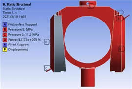
Figure 11 Constraint and loads of valve plates
Stress analysis results
It can be seen from the distribution of the valve plate's stress field (Figure 17) that the maximum stress of the valve body is 68.359MPa without considering the manufacturing error, which is less than the allowable stress specified in the standard.
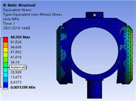
Figure 12 The diagram of the stress distribution of the valve plate
Analysis results of reliability
Figure 18 shows the equivalent stress by sampling 10,000 samples. According to the mathematical model obtained, the strength reliability of the valve plate of the spherical gate valve is close to 99.998%.
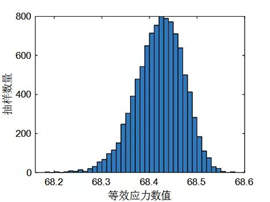
Figure 13 Equivalent stress distribution

Baltic Valve
BALTIC VALVE CO., LTD supplies superior quality industrial valves covering ball valves, globe valves, gate valves, check valves, plug valves, butterfly valves, marine valves, forging steel valve, filter, etc.
Stay Connected
Latest News


DBB Ball Valves Available from Workshop Stock
Jun 30, 2026
Contact Us
Baltic Valve Co., Ltd.
Add: Baltic Valve Park, Siming, Xiamen, China.
Tel: +86 592 8266 140
Fax: +86 592 8266 440
Mail: [email protected]
Website: https://www.baltic-valve.com
Copyright © 2017-2026 Baltic Valve Co., Ltd. All rights reserved. Privacy Policy | Terms of Service
Website Design & Support: jeawin.com