DBB and DIB Valves
There are two sealing structures of common seats for trunnion mounted ball valves.
(1) DBB valves (double block and bleed valves)
DBB valves are valves that have two valve seat sealing pairs, which can make the two ends of valves seal by pressure through discharging gas at the valve cavity between the two valve seat surfaces in the closed position.
(1) DBB valves (double block and bleed valves)
DBB valves are valves that have two valve seat sealing pairs, which can make the two ends of valves seal by pressure through discharging gas at the valve cavity between the two valve seat surfaces in the closed position.
(2) DIB valves (double isolation and bleed valves)
DIB valves are valves that have two valve seat sealing pairs. A single-source pressure seal can be provided through the discharge of the valve body cavity between the two valve seat sealing pairs in the closed position.
Pressure tests for DBB and DIB valves
Pressure tests for DBB and DIB valves
Pressure tests for DBB valves
Fill the valve and cavity with the experimental medium at the open state of the valve. Make the valve closed and the relief valve open. Excess test liquid can overflow from the valve cavity test interface. Apply pressure from both ends of the valve at the same time. The sealing performance can be known from the overflow at the valve cavity test interface.
Pressure tests for DIB valves
(1) DIB-1 valves with two-way double seats
A test should be conducted in two directions for every valve. Remove the pressure relief valve of the cavity if there is one. Fill the valve with the test medium at an open state till the test liquid overflows through the test interface of the valve cavity. Close the valve to test the leakage of the valve seat in the direction of the cavity. The test pressure should be applied to each end of the valve one by one in order to test the leakage of each valve seat upstream. Obtain the sealing performance of the valve seat based on the overflow at the valve cavity test interface. Later, test the downstream valve seat. Make the two ends of the valve open to fill the valve cavity with test media and then pressurize. Meanwhile, observe the leakage of each valve seat at both ends of the valve.
(2) DIB-2 valves with one-way single seats or one-way double seats
The two-way valve seat should be tested in two directions. Remove the pressure relief valve of the cavity if there is one. Fill the valve with the test medium at a half open state till the test liquid overflows through the test interface of the valve cavity. Close the valve to test the leakage of the valve seat in the direction of the cavity. The test pressure should be applied to each end of the valve one by one in order to test the leakage of each valve seat upstream. Obtain the sealing performance of the valve seat based on the overflow at the valve cavity test interface. As for the two-way sealed valve seat test of the valve cavity test, apply the test pressure to the valve cavity and the upstream end in sequence. Check the leakage at the downstream end of the valve.
Structures of DBB and DIB valves
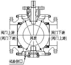
(1) DBB valves
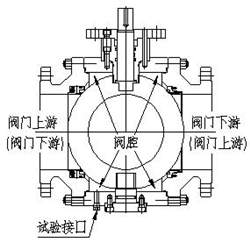
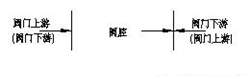
The above picture is the typical structure for DBB valves. The two ends of valves in the picture are marked with valve upstream and valve downstream, because we call the pressure injected end valve upstream and the other end downstream. In the pressure test, both ends of the DBB valve can be used upstream or downstream. The above picture can be simplified as follows:
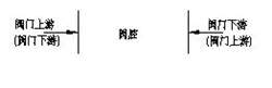
The two vertical lines in the above pictures indicate the two valve seats, and the direction of the arrow indicates the direction that needs to be sealed. In other words, when the valve is in the closed state and the valve cavity test interface is in the open state, both ends of the valve are pressurized at the same time (or pressurized separately), and the valve cavity test interface of the valve can detect whether the leakage is from each end to the valve cavity.
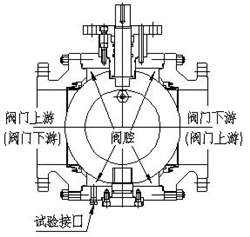
(2) DIB-1 valves with two-way double seats
The above picture shows the typical structure for DIB-1 valves. The above picture can be simplified as the following:
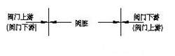
The two vertical lines in the above picture show the two valve seats, and the direction of the arrow indicates the place that needs to be sealed. In other words. In other words, each valve seat of the DIB-1 valve can withstand the pressure from the valve cavity or upstream and downstream of the valve without leakage. When the valve is in the closed state and the valve cavity test interface is in the open state, both ends of the valve are pressurized or they are pressurized separately; the valve cavity test interface of the valve can detect whether the leakage is from each end to the valve cavity. After that, release the pressure at both ends of the valve; pressurize from the valve cavity, and observe whether there is leakage at both ends of the valve.
Please note that because the pressure of the DIB-1 valve cavity cannot be automatically discharged to any end of the valve, when the valve temperature rises abnormally, the medium volume of the valve cavity increases, which forces the cavity pressure to increase. When the pressure is increased to a certain extent, the valve will be very dangerous. Therefore, a safety valve must be installed in the middle cavity of the DIB-1 valve.
Pressure tests for DIB valves
(1) DIB-1 valves with two-way double seats
A test should be conducted in two directions for every valve. Remove the pressure relief valve of the cavity if there is one. Fill the valve with the test medium at an open state till the test liquid overflows through the test interface of the valve cavity. Close the valve to test the leakage of the valve seat in the direction of the cavity. The test pressure should be applied to each end of the valve one by one in order to test the leakage of each valve seat upstream. Obtain the sealing performance of the valve seat based on the overflow at the valve cavity test interface. Later, test the downstream valve seat. Make the two ends of the valve open to fill the valve cavity with test media and then pressurize. Meanwhile, observe the leakage of each valve seat at both ends of the valve.
(2) DIB-2 valves with one-way single seats or one-way double seats
The two-way valve seat should be tested in two directions. Remove the pressure relief valve of the cavity if there is one. Fill the valve with the test medium at a half open state till the test liquid overflows through the test interface of the valve cavity. Close the valve to test the leakage of the valve seat in the direction of the cavity. The test pressure should be applied to each end of the valve one by one in order to test the leakage of each valve seat upstream. Obtain the sealing performance of the valve seat based on the overflow at the valve cavity test interface. As for the two-way sealed valve seat test of the valve cavity test, apply the test pressure to the valve cavity and the upstream end in sequence. Check the leakage at the downstream end of the valve.
Structures of DBB and DIB valves
(1) DBB valves
The above picture is the typical structure for DBB valves. The two ends of valves in the picture are marked with valve upstream and valve downstream, because we call the pressure injected end valve upstream and the other end downstream. In the pressure test, both ends of the DBB valve can be used upstream or downstream. The above picture can be simplified as follows:
The two vertical lines in the above pictures indicate the two valve seats, and the direction of the arrow indicates the direction that needs to be sealed. In other words, when the valve is in the closed state and the valve cavity test interface is in the open state, both ends of the valve are pressurized at the same time (or pressurized separately), and the valve cavity test interface of the valve can detect whether the leakage is from each end to the valve cavity.
(2) DIB-1 valves with two-way double seats
The above picture shows the typical structure for DIB-1 valves. The above picture can be simplified as the following:
The two vertical lines in the above picture show the two valve seats, and the direction of the arrow indicates the place that needs to be sealed. In other words. In other words, each valve seat of the DIB-1 valve can withstand the pressure from the valve cavity or upstream and downstream of the valve without leakage. When the valve is in the closed state and the valve cavity test interface is in the open state, both ends of the valve are pressurized or they are pressurized separately; the valve cavity test interface of the valve can detect whether the leakage is from each end to the valve cavity. After that, release the pressure at both ends of the valve; pressurize from the valve cavity, and observe whether there is leakage at both ends of the valve.
Please note that because the pressure of the DIB-1 valve cavity cannot be automatically discharged to any end of the valve, when the valve temperature rises abnormally, the medium volume of the valve cavity increases, which forces the cavity pressure to increase. When the pressure is increased to a certain extent, the valve will be very dangerous. Therefore, a safety valve must be installed in the middle cavity of the DIB-1 valve.
(2) DIB-2 valves with one-way single seats and one-way double seats
The above picture shows a typical structure for DIB-2 valves. The above picture can be simplified as follows:
The two vertical lines above indicates the two valve seats, and the direction of the arrow indicates the place which needs to be sealed. One of the valve seats of the DIB-2 valve can withstand the pressure from the valve cavity or the valve end in any direction without leakage; the other valve seat of the valve can only withstand the pressure from the valve end without leakage. When the valve is in the closed state and the valve cavity test interface is in the open state, pressurize the two ends of the valve at the same time or separately, and the valve cavity test interface can detect whether there is leakage from each end of the valve to the valve cavity. After that, when we experiment with a two-way valve seat, we should pressurize the valve cavity and the upstream of the valve separately to observe whether the downstream of the valve leaks. As shown in the picture above, pressurize the valve cavity and the left end of the valve, and observe the leakage at the right end of the valve.
Please note that when the pipeline requires the valve to be closed, the medium must not enter the downstream of the pipeline. At the same time, when the pressure in the cavity increases abnormally, the pressure can be automatically discharged to the upstream of the valve to protect the valve. Therefore, there will be a requirement for a direction for this type of valve during installation, and special attention must be paid. If the installation direction is reversed, the effect will be the same as that of DBB valves.

Baltic Valve
BALTIC VALVE CO., LTD supplies superior quality industrial valves covering ball valves, globe valves, gate valves, check valves, plug valves, butterfly valves, marine valves, forging steel valve, filter, etc.
Stay Connected
Latest News


DBB Ball Valves Available from Workshop Stock
Jun 30, 2026
Contact Us
Baltic Valve Co., Ltd.
Add: Baltic Valve Park, Siming, Xiamen, China.
Tel: +86 592 8266 140
Fax: +86 592 8266 440
Mail: [email protected]
Website: https://www.baltic-valve.com
Copyright © 2017-2026 Baltic Valve Co., Ltd. All rights reserved. Privacy Policy | Terms of Service
Website Design & Support: jeawin.com