Common Installation Issues of Cryogenic Valves in Petrochemical Plants and Solutions
Abstract: This paper analyzes the issue of frequent errors in the flow direction installation of cryogenic valves. By examining the structural characteristics and process design requirements of cryogenic gate valves, globe valves, ball valves, and butterfly valves, it proposes installation principles and solutions. The paper focuses on addressing problems in the design, manufacturing, installation, and management phases, aiming to provide guidance for the correct installation of cryogenic valves in petrochemical plants.
In petrochemical plants, including ethylene, propylene, liquefied natural gas (LNG) facilities, and coal chemical air separation and purification plants, a variety of cryogenic materials are used, which require the installation of cryogenic valves, such as gate valves, globe valves, check valves, ball valves, and butterfly valves. Cryogenic valves are typically defined as valves designed for operation at temperatures below -29°C. These valves have unique structural features and installation requirements, particularly concerning the flow direction. Improper flow direction installation can result in the valve failing to meet process requirements and may even lead to safety incidents. The root cause of this issue lies in the insufficient understanding of the structural characteristics and process requirements of cryogenic valves, as well as the lack of attention given to the design, manufacturing, installation, and management stages. This paper analyzes the characteristics of these valves and proposes principles and solutions for their proper flow direction installation.
In applications involving cryogenic media such as liquefied hydrocarbons, liquid nitrogen, and liquid ammonia, when a valve is closed, the medium remaining in the valve cavity can be affected by ambient temperature. As the medium heats up and vaporizes, it expands rapidly, causing an increase in pressure within the valve cavity. If the vaporized medium is not discharged from the valve cavity promptly, the pressure can rise to a level that may damage the valve. To prevent this, cryogenic valves, such as gate valves and ball valves, which have a sealed valve cavity when closed, must be equipped with a pressure relief device to avoid overpressure issues.
Given the low temperature of the conveyed medium, it is essential to prevent the sealing failure of the valve packing due to ice formation. For this purpose, the valve bonnet of gate valves, globe valves, ball valves, and butterfly valves should be designed with an extended bonnet structure to maintain a temperature above 0°C at the bottom of the stuffing box. The extended section of the bonnet refers to the portion between the top of the bonnet support and the bottom of the bonnet stuffing box, as well as the segment between the top of the lower bonnet bushing of a lifting stem valve, such as gate and globe valves, and the bottom of the stuffing box, or between the top of the lower bonnet bearing of a quarter-turn valve, such as ball and butterfly valves, and the bottom of the stuffing box. Additionally, to prevent condensed water from entering the insulation layer of the extended bonnet, a drip tray is placed at the extended neck of the bonnet.
A gate valve is a valve driven by a sliding valve disc or gate through a valve stem, with motion perpendicular to the flow direction of the medium. It features bidirectional sealing, excellent sealing performance, a small pressure drop in the fully open state, and a wide range of applicable sizes and pressures. Gate valves are primarily used to shut off the medium in the pipeline and are the most commonly used valves in engineering applications.
The typical structure of a cryogenic gate valve is shown in Figure 1. This valve has a double valve seat, and when closed, it forms a sealed space within the valve cavity. To prevent overpressure within the valve cavity, the pressure relief function is typically achieved by opening a pressure relief hole in the gate plate. The direction of pressure relief is toward the side where the pressure relief hole is located. Since the pressure relief hole is situated on the gate plate, the cryogenic gate valve cannot meet the requirements for bidirectional sealing and is limited to one-way sealing. When the valve is closed, the pressure-bearing (sealing) direction is opposite to the pressure relief direction. Therefore, the installation direction of the cryogenic gate valve should be determined based on the pressure-bearing direction when closed. Additionally, the cryogenic gate valve features an extended valve bonnet structure, and a drip tray is provided.
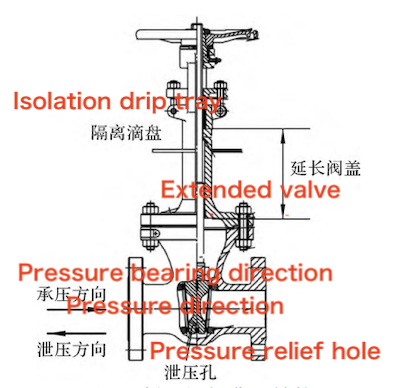
Figure 1 Typical structure of cryogenic gate valves
A globe valve is a valve in which the opening and closing part (valve disc) is driven by the valve stem and moves up and down along the axis of the valve seat (sealing surface). The valve stem of a globe valve has a relatively short stroke for opening or closing and provides a reliable shut-off function. Therefore, it is ideal for use as a shut-off valve and is also suitable for regulating or throttling flow. Globe valves rely on the forced seal of the valve disc, requiring significant force for opening and closing. As a result, they are generally not used for large-diameter or high-pressure pipelines.
The typical structure of a cryogenic globe valve is shown in Figure 2. This valve has a single-seat seal. When closed, it does not form a sealed space within the valve cavity, so no pressure relief device is necessary. The pressure-bearing (sealing) direction of the cryogenic globe valve is the same as that of a standard temperature globe valve, and there are no special installation requirements. The cryogenic globe valve features an extended valve bonnet structure, and a drip tray is provided.
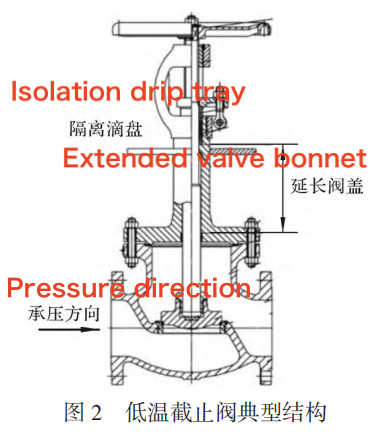
Figure 2 Typical structure of cryogenic globe valves
The opening and closing part of a ball valve is a sphere, which rotates 90° around the axis of the valve stem to open or close the valve. The ball valve is characterized by bidirectional sealing, excellent sealing performance, low flow resistance, compact structure, and ease of operation. It is primarily used to shut off, distribute, and change the flow direction of the medium in the pipeline. Ball valves designed with a "V"-shaped opening also provide effective flow regulation. The typical structure of a cryogenic ball valve is shown in Figure 3. The cryogenic ball valve features a double valve seat. When the valve is closed, a sealed space is formed in the valve cavity.
To prevent overpressure in the valve cavity, two methods are commonly used to achieve pressure relief:
- Opening a pressure relief hole on the ball, with the relief direction corresponding to the side of the hole
- Designing a pressure relief valve seat, with the relief direction being either upstream or downstream of the seat
For cryogenic ball valves with a pressure relief hole on the ball, the valve can only provide one-way sealing, as it cannot meet the requirements for bidirectional sealing. When the valve is closed, the pressure-bearing (sealing) direction is opposite to the pressure relief direction. Therefore, the installation direction of the cryogenic ball valve should be determined based on the pressure-bearing direction when it is closed. Additionally, the cryogenic ball valve includes an extended valve bonnet structure, and a drip tray is provided.
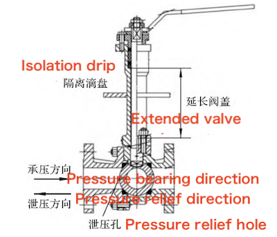
Figure 3 Typical structure of cryogenic ball valves
The opening and closing part of the butterfly valve is a disc-shaped butterfly plate, which rotates around its axis within the valve body to achieve opening, closing, or regulation. The butterfly valve is characterized by a simple structure, low flow resistance, fast operation, low opening and closing torque, compact size, and light weight. However, its sealing performance is inferior to that of the gate valve, and it is typically used on large-diameter pipes with low sealing requirements. The typical structure of the cryogenic butterfly valve is shown in Figure 4.
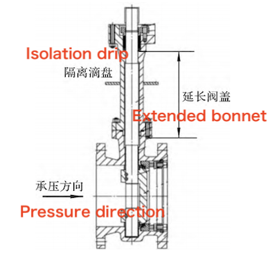
Figure 4: Typical structure of cryogenic butterfly valves
When the cryogenic butterfly valve is closed, no enclosed space is formed within the valve cavity, so there is no need for a pressure relief device. The pressure-bearing (sealing) direction of the cryogenic butterfly valve when closed is the same as that of a standard temperature butterfly valve, and no special installation requirements exist. The cryogenic butterfly valve features an extended valve bonnet structure and is equipped with a drip tray.
Cryogenic gate valves, globe valves, ball valves, and butterfly valves with extended valve bonnets should be installed on horizontal pipes, with the valve stem oriented vertically upward. If, due to special circumstances, the valve stem cannot be oriented vertically upward, the operating valve stem direction should be at least 45° from the horizontal plane, as shown in Figure 5.
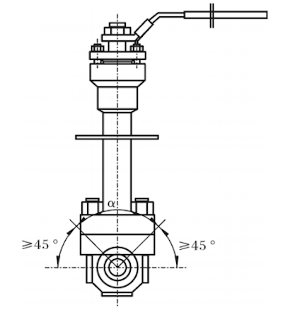
Figure 5: Installation of Cryogenic Valve Stem
For cryogenic valves, such as cryogenic globe valves and butterfly valves, which do not require valve cavity pressure relief, the installation flow direction follows the same guidelines as conventional valves. During installation, they can be positioned according to the flow direction arrow marked on the valve. Standard gate valves or ball valves can seal in both directions, so they typically do not have a flow direction arrow on the valve body. However, for cryogenic gate valves and ball valves with pressure relief holes or pressure relief valve seats, the pressure relief direction is typically marked on the valve body. The pressure relief direction points toward the pressure-bearing side. It is important to note that this direction is not the installation direction of the valve or the flow direction of the medium. The settings for the pressure relief hole and the pressure relief direction are shown in Figures 1 and 3, with the actual valve not depicted in Figure 6.
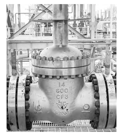
Figure 6: Cryogenic Gate Valve
As shown in Figure 6, there is an arrow indicating the pressure relief direction on the valve body, along with a "vent" label. Therefore, when installing the valve on-site, it cannot be installed based on the principle that the arrow on the valve body aligns with the flow direction of the medium. The correct installation principle is that, after installation, the pressure relief arrow should point toward the side with the higher pressure when the valve is closed. This is because the sealing surface on the low-pressure side of the valve plays the primary sealing role in this state. If the relief hole is on the low-pressure side, the medium will leak from the high-pressure side to the low-pressure side through the pressure relief hole, causing the valve to fail to seal properly.
Taking a simple low-temperature system as an example, the pressure relief direction of the cryogenic gate valve and cryogenic ball valve is analyzed. The process for the low-temperature system is shown in Figure 7. In the system illustrated in Figure 7, the pressure relief direction of the cryogenic valve has four possible scenarios:
Valve V1: This valve is located in the main pipeline and is normally open. When the valve is closed and cuts off the flow, the upstream side of the valve is the high-pressure side (the upstream and downstream are defined based on the medium's flow direction during normal operation). There is no medium downstream, making it the low-pressure side. Therefore, when the valve is closed, the pressure in the valve cavity should be released toward the upstream, as shown in Figure 7. The pressure relief direction is toward the upstream.
Valves V21 and V22: These valves are located in front of and behind the regulating valve. They are normally open. When the regulating valve needs repair, valves V21 and V22 are closed, and the regulating valve is removed after draining the material from the pipeline. The medium is upstream of valve V21, and the downstream is connected to the atmosphere. The pressure in the cavity must be released into the upstream pipeline and not into the atmosphere, as shown in Figure 7. The pressure relief direction is toward the upstream. For valve V22, the upstream is connected to the atmosphere, and the downstream is connected to a closed pipeline. Therefore, the pressure in the cavity must be released into the downstream closed pipeline and not into the atmosphere, as shown in Figure 7. The pressure relief direction is toward the downstream.
Valves V31 and V32: These valves are connected to equipment. When the valve is closed, the pressure in the cavity should be released into the equipment. Therefore, the pressure relief direction of valve V31 is toward the upstream, and the pressure relief direction of valve V32 is toward the downstream.
Valve V4: This is a shower valve. The downstream of the valve is connected to the atmosphere. When the valve is closed, the medium in the cavity should be released into the pipeline and not into the atmosphere. As shown in Figure 7, the pressure relief direction is toward the upstream.
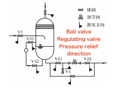
Figure 7: Cryogenic System Flow
For the special installation requirements of gate valves, globe valves, ball valves, and butterfly valves in cryogenic pipelines, corresponding measures can be taken at various stages, including design, manufacturing, installation, and operation management, to ensure the correct installation of cryogenic valves.
During the process design phase, for low-temperature valves such as gate valves and ball valves that require central cavity pressure relief, the pressure relief direction is specified in the process and instrument flow diagram, based on the location, function, and opening/closing status of the cryogenic valve. The pressure relief direction can be indicated by arrows on the valve, as shown in Figure 7. During piping design, special legend symbols for cryogenic gate valves and ball valves are created in the 3D software, with the pressure relief direction clearly indicated in the legend. When creating the 3D model, the appropriate legend symbol is selected based on the pressure relief direction requirements in the process and instrument flow chart. This ensures that, when the pipeline is exported, the pressure relief direction of the cryogenic valve is reflected in the isometric diagram, providing a foundation for the subsequent valve construction and installation.
When preparing the valve procurement technical specifications, for cryogenic valves with pressure relief direction requirements, manufacturers are required to cast the pressure relief direction on the valve body and mark and explain it in locations such as the drip tray, which are less likely to be obstructed. This helps facilitate inspection after installation. In the pipeline design documentation, cryogenic valves with pressure relief direction requirements are explained in detail to provide a basis for future construction and operation management.
For cryogenic valves, the manufacturer must cast the pressure relief direction of valves with specific pressure relief requirements on the valve body, following the guidelines provided in the valve procurement technical specification. Additionally, the pressure relief direction should be marked and explained in the drip tray and other areas that are not easily obstructed. The submitted instruction manual should include detailed explanations of the installation requirements for cryogenic valves, particularly regarding the installation direction, to provide technical support for on-site construction, installation, and subsequent maintenance and replacement.
Upon the arrival of cryogenic valves, each unit must be inspected, focusing on verifying that the pressure relief direction and markings are correct and that the instruction manual and other materials are complete. During the on-site pressure and sealing tests, the test pressure loading direction should be determined based on the cryogenic valve’s pressure relief direction. After passing the inspection tests, the cryogenic valves should be stored separately from other valves and distributed for installation accordingly. Before installation, an on-site design briefing should be conducted to explain the installation requirements of the cryogenic valve. This briefing should include relevant personnel from the design, construction, and supervision teams, and the meeting minutes should be recorded. Additionally, on-site construction personnel must be instructed to correctly install the valve according to the pressure relief direction information displayed in the process and instrument flow chart, axonometric diagram, and the pressure relief arrow on the valve body.
During the "three checks and four determinations" stage of the equipment, cryogenic valves with pressure relief direction requirements should be inspected individually to ensure that the pressure relief direction aligns with the design documents, such as the process and instrument flow chart, axonometric diagram, and others. During maintenance shutdowns, if a cryogenic valve needs to be disassembled, repaired, or replaced, the pressure relief direction should be verified once again according to the design documents, valve identification, and instruction manual to ensure the correct installation of the valve pressure relief.
Cryogenic gate valves, globe valves, ball valves, and butterfly valves commonly used in petrochemical plants have structural features such as extended valve bonnets and drip trays. Valves with closed valve cavities (such as gate valves and ball valves) must be equipped with pressure relief devices. Cryogenic valves with extended valve bonnets should be installed on horizontal pipelines, or the valve stem should be positioned at an angle of no less than 45° to the horizontal plane. The installation flow direction of cryogenic globe valves and butterfly valves follows the same guidelines as conventional valves; however, for cryogenic gate valves and ball valves, it is essential to ensure that the pressure relief device arrow points toward the side with higher pressure when the valve is closed. Given the potential for errors in the flow direction installation of cryogenic valves, it is recommended to address this issue through a comprehensive approach covering process design, pipeline design, valve manufacturing, installation, construction, and operation management to ensure the correct installation of cryogenic valves.


