Forced Sealed Valves for Natural Gas Pipelines
A forced sealed valve is also known as a double block and double bleed valve, which was first used for oil depots in the airport, and was mainly used in metering systems, metering calibration systems, mixed transportation systems with multi branches, tank partitions, aviation fuel storage and transportation, frequently operated feeding and unloading systems. Later, it was gradually used for oil and gas pipelines. Although the amount of the forced sealed valve in the system is not great, its effect is very obvious.
The development of the forced sealed valve
In 1946, the American General Valve Company introduced the first generation A series of forced sealed valves, but there were many defects for this series of valves. The operating mechanism was in the medium. If the operating mechanism was repaired or maintained, it must be shut down, which required a lot of manpower, material resources and time; in addition, the sealing surface was sealed by soft sealing; the valve was not designed with a fire safety structure. For this reason, in 1953, the American General Valve Company introduced an improved B series of valves. The valve was improved. First, the operating mechanism was completely isolated from the conveying medium through the gland and packing seal. Second, the soft seal was fixed in the groove of the sliding plate through bonding, and the soft seal was protected by the metal sliding plate. Third, fire safety was designed for the forced sealed valve. By 1958, the company launched a new generation of products that could be repaired online without shutting down the pipeline. After years of development, the current forced sealed valve has been greatly improved in terms of sealing of valve bodies, operating mechanism structure, bonding of soft seals, fire protection, heat release systems, and coatings of valve components.
The structure and working principles of the forced sealed valve
A forced sealed valve is mainly composed of valve upper bonnets, bottom bonnets, sliding plates, plugs and operating mechanisms. The connection between the seal (sliding vanes) and the plug of the forced sealed valve is guide rail structure. When the valve is opened, the plug is first raised to a height by the transmission mechanism. As the cock is lifted, the two sliding plates are gradually pulled back by the cock to the center of the valve. When the sealing surface of the sliding plate is completely separated from the sealing surface of the valve body and forms a certain gap, the plug along with the sliding plate is rotated at an angle of 90 through the transmission mechanism until the valve opens. When the valve is closed, the plug and sliding plate are rotated by 90° through the transmission mechanism. The valve is closed, but the sealing is not formed. The plug is continued to be pushed down through the transmission mechanism. As the plug moves downward, the sliding plate is pushed closer to the sealing surfaces on both sides of the valve body until the elastic sealing ring on the sliding plate is evenly squeezed onto the sealing surfaces on both sides of the valve body to form a seal. The key technologies of forced sealing valves mainly include the following points:
1. The sealing for the flange
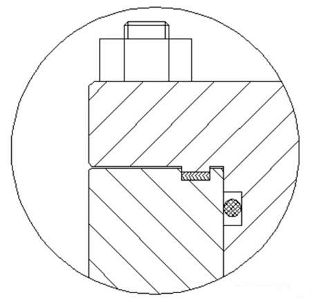
Most forced sealed valves are used for aviation kerosene, natural gas, liquefied petroleum gas and refined oil. Since aviation kerosene, natural gas and other media have great permeability, and are flammable and explosive, it is necessary to completely prevent the medium from leaking. The double sealing structure of an O-ring and a spiral wound gasket is adopted at the flange, as shown in the figure.
2. The packing
In the opening and closing process of valves, the valve spool of the forced sealed valve not only moves up and down but also rotates. In addition to the particularity of the medium, the sealing of the packing is required to be safe and reliable, and the combined sealing method of inner and outer O rings and packing seals is often used.
3. Overpressure relief functions in the valve cavity
Double sealed valves must have relief devices and functions. The discharged pressure difference is caused by changes in the ambient temperature. When the double sealed valve is closed, the medium in the valve cavity expands with the increase of ambient temperature, and the pressure gradually rises. If the pressure difference is not released in time, it will have a serious impact on the operation of the valve, and breaking due to expansion will even happen, causing serious hidden dangers to the safety of the system. There are usually three types of pressure relief systems for double block and double bleed valves, which are as follows:
(1) Manual pressure relief systems for manually operated valves
A needle valve is usually installed on the valve body. When the valve is closed, the needle valve is opened to discharge the medium in the valve body to the upstream of the pipeline or the atmosphere.
(2) Differential thermal pressure relief systems for manual and electric operated valves
It is a piping system with a one-way valve. The manual relief valve, three-way, one-way valve, and isolation valve constitute a differential thermal pressure relief system. The isolation valve remains open. When the valve is closed, the overpressure in the cavity of the valve body is discharged to the upstream of the valve and connected to the pipeline through the one-way valve. Opening the manual relief valve can check the sealing effect of the valve, and the manual relief valve must be closed when the valve is opened.
(3) Automatic pressure relief systems for electrically operated valves
When the valve is closed, the pressure relief valve is automatically opened through the operating mechanism, and the valve cavity is connected to the upstream of the pipeline or outside world.
4. The operating mechanism and self-locking of the valve
The operating mechanism of the double block and double bleed valve adopts a unique L shaped groove structure, which separates the axial linear movement of the plug from the 90° rotational movement, making the valve’s operation flexible and easy. The plug first moves in a straight line and then rotates. In order to reduce the number of turns of the handwheel, generally, the trapezoidal thread of the valve stem and screw sleeve adopts double ends or multi ends. The gear transmission mechanism has the function of self-locking, and the trapezoidal thread is a heavy-duty trapezoidal thread, which can bear a greater load. There is another valve whose guide groove is designed in an S shape, which is almost an S-shaped spiral on the cylindrical surface of the screw sleeve. The principle of its action is that the plug initially moves in a straight line, and then it performs both a straight line and a rotating motion. The guide key bears greater shearing force, and high requirements are put forward for the strength of the guide key. A larger stroke should be designed for rotation. Otherwise, it is easy to cause friction between the soft sealing surface and sealing surface of the valve body, resulting in greater operating torque and shortening of the service life of the valve. Therefore, the S type guide groove structure has fatal design flaws.
5. Special process treatment of key components
Special treatment is required for the key parts of the valve due to the harsh working conditions of the valve. After mechanical processing the inner cavity of the valve, the surface is plated with hard chromium, so that the inner cavity of the valve has the properties of rust resistance, scouring resistance, wear resistance and corrosion resistance. After the sliding plate is machined (before pressing the fluorine rubber), it is treated with hard chromium plating to make the metal sealing surface of the sliding plate have rust resistance, scouring resistance, abrasion resistance and corrosion resistance. The plug is nickel-plated after being machined, which makes the plug, upper and lower shafts resistant to rust and corrosion. After the valve stem is roughly processed, it is adjusted. After fine finishing, it is nitrided to improve the anti-seize and anti-wear performance of the screw sleeve. The L-shaped guide groove on the screw sleeve and the head of the guide key are quenched after processing to improve the wear resistance and ensure that the guide key can slide freely in the guide groove.
The development of the forced sealed valve
In 1946, the American General Valve Company introduced the first generation A series of forced sealed valves, but there were many defects for this series of valves. The operating mechanism was in the medium. If the operating mechanism was repaired or maintained, it must be shut down, which required a lot of manpower, material resources and time; in addition, the sealing surface was sealed by soft sealing; the valve was not designed with a fire safety structure. For this reason, in 1953, the American General Valve Company introduced an improved B series of valves. The valve was improved. First, the operating mechanism was completely isolated from the conveying medium through the gland and packing seal. Second, the soft seal was fixed in the groove of the sliding plate through bonding, and the soft seal was protected by the metal sliding plate. Third, fire safety was designed for the forced sealed valve. By 1958, the company launched a new generation of products that could be repaired online without shutting down the pipeline. After years of development, the current forced sealed valve has been greatly improved in terms of sealing of valve bodies, operating mechanism structure, bonding of soft seals, fire protection, heat release systems, and coatings of valve components.
The structure and working principles of the forced sealed valve
A forced sealed valve is mainly composed of valve upper bonnets, bottom bonnets, sliding plates, plugs and operating mechanisms. The connection between the seal (sliding vanes) and the plug of the forced sealed valve is guide rail structure. When the valve is opened, the plug is first raised to a height by the transmission mechanism. As the cock is lifted, the two sliding plates are gradually pulled back by the cock to the center of the valve. When the sealing surface of the sliding plate is completely separated from the sealing surface of the valve body and forms a certain gap, the plug along with the sliding plate is rotated at an angle of 90 through the transmission mechanism until the valve opens. When the valve is closed, the plug and sliding plate are rotated by 90° through the transmission mechanism. The valve is closed, but the sealing is not formed. The plug is continued to be pushed down through the transmission mechanism. As the plug moves downward, the sliding plate is pushed closer to the sealing surfaces on both sides of the valve body until the elastic sealing ring on the sliding plate is evenly squeezed onto the sealing surfaces on both sides of the valve body to form a seal. The key technologies of forced sealing valves mainly include the following points:
1. The sealing for the flange
Most forced sealed valves are used for aviation kerosene, natural gas, liquefied petroleum gas and refined oil. Since aviation kerosene, natural gas and other media have great permeability, and are flammable and explosive, it is necessary to completely prevent the medium from leaking. The double sealing structure of an O-ring and a spiral wound gasket is adopted at the flange, as shown in the figure.
2. The packing
In the opening and closing process of valves, the valve spool of the forced sealed valve not only moves up and down but also rotates. In addition to the particularity of the medium, the sealing of the packing is required to be safe and reliable, and the combined sealing method of inner and outer O rings and packing seals is often used.
3. Overpressure relief functions in the valve cavity
Double sealed valves must have relief devices and functions. The discharged pressure difference is caused by changes in the ambient temperature. When the double sealed valve is closed, the medium in the valve cavity expands with the increase of ambient temperature, and the pressure gradually rises. If the pressure difference is not released in time, it will have a serious impact on the operation of the valve, and breaking due to expansion will even happen, causing serious hidden dangers to the safety of the system. There are usually three types of pressure relief systems for double block and double bleed valves, which are as follows:
(1) Manual pressure relief systems for manually operated valves
A needle valve is usually installed on the valve body. When the valve is closed, the needle valve is opened to discharge the medium in the valve body to the upstream of the pipeline or the atmosphere.
(2) Differential thermal pressure relief systems for manual and electric operated valves
It is a piping system with a one-way valve. The manual relief valve, three-way, one-way valve, and isolation valve constitute a differential thermal pressure relief system. The isolation valve remains open. When the valve is closed, the overpressure in the cavity of the valve body is discharged to the upstream of the valve and connected to the pipeline through the one-way valve. Opening the manual relief valve can check the sealing effect of the valve, and the manual relief valve must be closed when the valve is opened.
(3) Automatic pressure relief systems for electrically operated valves
When the valve is closed, the pressure relief valve is automatically opened through the operating mechanism, and the valve cavity is connected to the upstream of the pipeline or outside world.
4. The operating mechanism and self-locking of the valve
The operating mechanism of the double block and double bleed valve adopts a unique L shaped groove structure, which separates the axial linear movement of the plug from the 90° rotational movement, making the valve’s operation flexible and easy. The plug first moves in a straight line and then rotates. In order to reduce the number of turns of the handwheel, generally, the trapezoidal thread of the valve stem and screw sleeve adopts double ends or multi ends. The gear transmission mechanism has the function of self-locking, and the trapezoidal thread is a heavy-duty trapezoidal thread, which can bear a greater load. There is another valve whose guide groove is designed in an S shape, which is almost an S-shaped spiral on the cylindrical surface of the screw sleeve. The principle of its action is that the plug initially moves in a straight line, and then it performs both a straight line and a rotating motion. The guide key bears greater shearing force, and high requirements are put forward for the strength of the guide key. A larger stroke should be designed for rotation. Otherwise, it is easy to cause friction between the soft sealing surface and sealing surface of the valve body, resulting in greater operating torque and shortening of the service life of the valve. Therefore, the S type guide groove structure has fatal design flaws.
5. Special process treatment of key components
Special treatment is required for the key parts of the valve due to the harsh working conditions of the valve. After mechanical processing the inner cavity of the valve, the surface is plated with hard chromium, so that the inner cavity of the valve has the properties of rust resistance, scouring resistance, wear resistance and corrosion resistance. After the sliding plate is machined (before pressing the fluorine rubber), it is treated with hard chromium plating to make the metal sealing surface of the sliding plate have rust resistance, scouring resistance, abrasion resistance and corrosion resistance. The plug is nickel-plated after being machined, which makes the plug, upper and lower shafts resistant to rust and corrosion. After the valve stem is roughly processed, it is adjusted. After fine finishing, it is nitrided to improve the anti-seize and anti-wear performance of the screw sleeve. The L-shaped guide groove on the screw sleeve and the head of the guide key are quenched after processing to improve the wear resistance and ensure that the guide key can slide freely in the guide groove.

Baltic Valve
BALTIC VALVE CO., LTD supplies superior quality industrial valves covering ball valves, globe valves, gate valves, check valves, plug valves, butterfly valves, marine valves, forging steel valve, filter, etc.
Stay Connected
Latest News


DBB Ball Valves Available from Workshop Stock
Jun 30, 2026
Contact Us
Baltic Valve Co., Ltd.
Add: Baltic Valve Park, Siming, Xiamen, China.
Tel: +86 592 8266 140
Fax: +86 592 8266 440
Mail: [email protected]
Website: https://www.baltic-valve.com
Copyright © 2017-2026 Baltic Valve Co., Ltd. All rights reserved. Privacy Policy | Terms of Service
Website Design & Support: jeawin.com